4-Circle Furnace Controllers
Instruction Manual
Procedure for starting the controller

- Install the furnace on the experimental setup.
- Connect to the furnace the vacuum gauge, the two thermocouples, the power supply of the heater. The water safety device has to be plugged to the distribution board of the experimental setup. Plug the control unit into a 230 V/16 A socket, check that the white indicator light is on.
Note: all connectors are different to avoid any inversion. - Connect the vacuum hose to the cooling circuit tubes.
- Install the sample by removing the sphere and the vanadium thermal shields.
- Replace the sphere and the shields and start the vacuum pump. The vacuum drop can take some time - it depends on the sample.
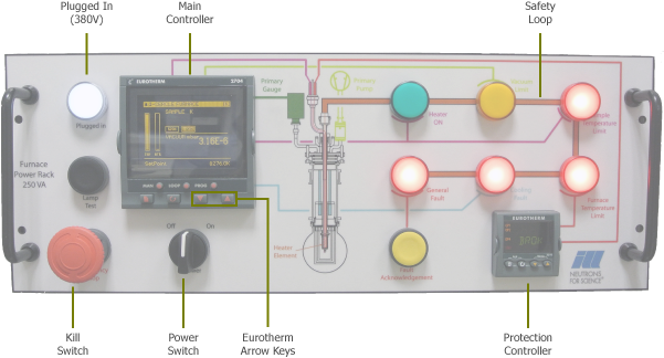
- Start the control unit by actuating the "power on" switch and wait until the two controllers are operating. The vacuum value is displayed on the controller.
- The indicator lights on the safety loop are on, and then off when the safety thresholds are reached (General Fault remains on).
- Pressing "Fault Acknowledgement" cancels the general faults unless a condition is not fulfilled.
- Indicator "Heater ON": when this indicator light is switched on, all safety conditions are fulfilled. You can start increasing the temperature if you have incremented a set threshold
- Emergency Stop: to be used only in case of an emergency stop.
Cooling fault:
- A red indicator light switched off means water circulation is in operation.
- If there is a very short interruption (less than 12s), the indicator light remains off, i.e. heating is not cut off.
- If the interruption lasts more than 12s and up to 2 mn22s, the indicator light comes on and heating is cut off. The controller displays "Cooling Alarm".
- If the interruption is longer than 2mn22s, the indicator light comes on, then heating is cut off but a reset will be required to start heating again. The controller displays "Cooling Fault".
Sample temperature limit:
- A red indicator light switched off means under the safety threshold set by the user (between 273 and 1100 K).
Furnace temperature limit:
- A red indicator light switched off means under the safety threshold set in the program (1120 K).
Vacuum limit:
- An orange indicator light switched on means that the vacuum pressure is between the atmospheric pressure and 9.99 10-1 mbar and it is possible to heat up to 523 K.
- An orange indicator light switched off means that heating is possible up to 1 100 K (the vacuum pressure is below the threshold of 9.99 10-1 mbar).
N.B.: Authorisation to heat is given when all the red lights of the safety loop are off.
 (svg - 144 Ki)
Use of the 2704 controller
You can enter the setpoint with the computer of the instrument. The heating setpoint can also be directly and manually increased or decreased by using the arrow keys located on the 2704 controller. Whichever method you use, the setpoint will be displayed on the controller’s screen and the furnace will start heating if the safety conditions are met.
It is highly recommended that you proceed in stages when going up to a high temperature.
This is a good way to extend the lifetime of the heater.
How to stop heating
Enter the setpoint 273 K and wait until the temperature reaches 423 K to cut off the water cooling system and stop the vacuum pumping, so that the atmospheric pressure can be recovered in the vacuum vessel.
PLC Registers (Eurotherm 2704 Controller)
| Description | Read | Write | Address |
|---|---|---|---|
| Sample temperature (K) | X | 1 | |
| Temperature setpoint (K) | X | X | 2 |
| Output power (W) | X | 3 | |
| Vacuum pressure (mbar) | X | 6178 | |
| Vacuum pressure threshold (mbar) | X | 9235 | |
| Sample temperature limit (K) | X | 9225 | |
| Furnace temperature limit (K) | X | 9230 | |
| Temperature safety limit (K) | X | 9240 | |
| Max allowed temperature when 0.01 < p < 0.1 mbar | X | 9245 | |
| Max allowed temperature when p < 0.01 mbar | X | 9250 | |
| Required vacuum pressure for starting heating (mbar) | X | 11730 | |
| Maximum time during which water cooling can be absent (min) | X | 105 | |
| Time after which water cooling raises a default (min) | X | 11795 | |
| Firmware version | X | 9295 |