Sample Sticks for Cryostats
Sample sticks available from the pool for high-pressure cells
Several sticks are used to install the continuously loaded and clamped cells inside our cryostats. These sticks are selected and booked by our staff when a pressure cell is reserved for an experiment. These sticks fit into our standard "Orange" cryostats.
The pressure cells are available on request. Sufficient advance notice to sane(at)ill.fr is required for their reservation and preparation.
WARNING: samples which crystallise under pressure must not be injected through sample sticks to avoid blockages. In this specific case, only clamps or cells with an in-situ separator can be used.
Code | Temperature Range (K) | Maximum Pressure (kbar) | Calorimeter Ø (mm) | Type, Comment |
|---|---|---|---|---|
187ILHP49 | 1.5 - 320 | ? | Ø49 | |
188ILHP49 | 1.5 - 320 | ? | Ø49 | |
221ILHP49 | 1.5 - 320 | 0.5 | Ø49 | with Nb cell adjustable in height |
190ILHP49 | 1.5 - 320 | 1.5 | Ø49 | Stainless steel gas pressure cell, with heated capillary |
| 1.5 - 320 | 2.5 | Ø70 | for gas pressure cell 02PGAL15 | |
216ILHP49 | 1.5 - 320 | 3 | Ø49 | with CuBe gas pressure cell |
| 149ILHP49 | 1.5 - 320 | 5 | Ø49 | with optical fibre and sapphire window to illuminate the sample (10PL70TZ4) |
189ILHP49 | 1.5 - 320 | (5 ?) | Ø49 | liquid pressure cell, with heated two-way capillaries |
| 1.5 - 320 | 5 | Ø49 | with Al gas pressure cell | |
| 1.5 - 320 | 5 | Ø70 | for Al 7049 T6 gas pressure cell | |
| 1.5 - 550 | 7 | Ø49 | with gas pressure cell | |
217ILHP49 | 1.5 - 320 | 7 | Ø49 | with TiZr gas pressure cell |
| 1.5 - 550 | 7 | Ø49 | 7 kbar liquid pressure cell, with insulated heated capillary | |
| 1.5 - 550 | 7 | Ø49 | 7 kbar liquid pressure cell, with insulated heated capillary | |
| 1.5 - 320 | 7 | Ø70 | for liquid pressure cell | |
| 1.5 - 320 | 7 | Ø70 | for circulating a liquid sample | |
| 1.5 - 550 | 7 | Ø70 | 7 kbar liquid pressure cell, with insulated heated capillary | |
| 1.5 - 550 | 7 | Ø70 | 7 kbar liquid pressure cell, with insulated heated capillary + 2 wires | |
| 1.5 - 550 | 7 | Ø70 | 7 kbar liquid pressure cell, with insulated heated capillary + 4 wires | |
| 1.5 - 550 | 7 | Ø70 | 7 kbar liquid pressure cell, with insulated heated capillary | |
| 1.5 - 550 | 7 | Ø100 | 7 kbar liquid pressure cell, with insulated heated capillary | |
| 1.5 - 550 | 10 | Ø49 | 10 kbar pressure cell, with insulated heated capillary | |
| 1.5 - 550 | 10 | Ø70 | 10 kbar pressure cell, with insulated heated capillary | |
222ILHP49 | 1.5 - 320 | 0.1 - 12 | Ø49 | with in-situ 4 Tons press |
| 1.5 - 320 | 15 | Ø70 | for clamped cells, ≈20% pressure loss at lowest temperature | |
| 1.5 - 320 | 15 | Ø49 | for clamped cells, ≈20% pressure loss at lowest temperature |
Instruction Manual
Schematic view of a high-pressure stick
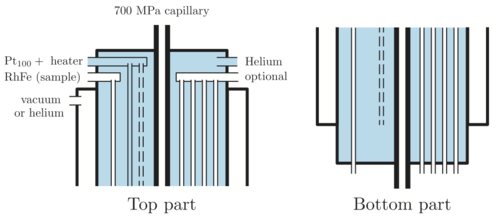
Schematic view of a high-pressure stick with insulated heated capillary for liquid pressure cells. The 700 MPa capillary is thermalised with exchange gas using a Pt100 and a Thermocoax heater. The stick is decoupled from the sample volume with an annular space under vacuum. Optionally, coaxial cables, wires or optical fibres can be brought to the sample space.
Procedure for installing the stick in the cryostat
- Connect the pressure cell to the capillary of the stick and verify the tightness (up to 700 MPa).
- Before inserting the stick in the sample bore of the cryostat, pump the annular isolation volume via the black vacuum valve to better than 10-6 mbar using a turbo-pump. Be sure to use a flexible line that has NEVER been used for pumping helium.
- Flush out the internal volume of the stick using pure helium gas from the liquid helium dewar:
- Connect one port of the blue 3-way valve of the stick to a primary pump.
- Connect the second port of the 3-way valve to the gas outlet of the dewar while keeping the valve of the dewar closed.
- Start the primary pump.
- Rotate the 3-way valve to evacuate the inner space.
- Close the 3-way valve (middle position) and wait for 5 minutes. Check that there is no pressure rise on the gauge of the pumping group. If the pressure rises, there is a leak in the system. Verify all connections and in particular the O-ring joints of the Wilson seals.
- Open the dewar valve to fill the inner volume of the stick with gas. When the pressure is equal to the atmospheric pressure, close the dewar valve.
- Repeat the operations 4) to 6) two times.
- Rotate the 3-way valve to evacuate the inner space.
- Open the dewar valve to fill the volume of the pipe up to the 3-way valve with gas.
- Rotate the 3-way valve to fill the inner volume of the stick with about 10 cc of gas, i.e. about 10 cm of the pipe.
- Insert the stick in the cryostat:
- If the actual regulation temperature is below 10 K, change the setpoint to 10 K.
- Connect a primary pump to the sample room valve (3-way blue valve) and start the pump.
- Turn the 3-way valve of the cryostat down (“arrow down”) to fill the sample room with helium gas and leave it in this position.
- Remove the flange, introduce the sample stick into the sample room and pump it by positioning the 3-way valve up (“arrow up”).
- Close the sample room by closing the 3-ways valve (horizontal position).
- Prepare 20 cc of exchange helium gas, and introduce them via the sample valve. 20 cc of exchange gas correspond to the volume of the tail of a pressurising bladder or 20 cm of the flexible tube connected to the dewar..
- Connect the dedicated temperature controller to the regulation socket (12-pin Jaeger). Verify that the Pt100 thermometer indicates the ambient temperature and test that the heating and regulation are operational by heating the capillary to 295 K. The controller must be set to regulate the temperature with a maximum current of 400 mA and a maximum power of 12 W. The settings depend on the controller used:
- LakeShore 336: Heater Resistance: 50 Ohms, Max Current: User, User Max Current: 0.400 A, Heater Range: High
- LakeShore 340: Heater: 80 Ohms, Max Heater I: User, Max I: 0.400 A, Max Range: 12 W - Connect the cryostat temperature controller to the sample socket (8-pin Jaeger). Check that the calibration curve selected in the LakeShore corresponds to the one of the stick by visiting the web page of the stick. Verify that the thermometer indicates the room temperature.
Procedure for cooling the sample down to 40 K
In most cases, the required sample temperature is greater than 40 K. Good results are obtained with a capillary maintained at 295 K and surrounded by an insulating vacuum of ≈10−6 mbar. These settings assume that helium is pumped out of the cryostat with a 100 m3/h dry helium pump from Adixen or a 40 m3/h oil pump.
- Check that the temperature of the high-pressure capillary is maintained at 295 K as described in item 5 above.
- Apply the desired pressure and check that it will be maintained during cooling.
- Change the regulation setpoint of the cryostat to a value greater than 40 K.
- Start cooling with a cold-valve set to 40 mbar. The high-pressure stick brings heat and the cool-down time increases by a factor of ≈2, so be patient.
- Once the temperature is reached by the sample (not the regulation i.e. the heat exchanger), tune the cold-valve to 2 mbar or even less to reduce the He consumption (reduce the He flow until a heating power of 150 mW is displayed on the regulator of the cryostat).
From the tests carried out with Ø70 cryostat and cryofurnace, the base temperature reached with the high-pressure capillary regulated at 295 K is slightly below 40 K. After switching the heater off, the base temperature decreases slightly further.
Procedure for cooling the sample down to 1.8 K (after having cooled down to 40 K as described above)
To reach temperatures below 40 K, it is necessary to stop heating the capillary and fill the annular space of the stick with ≈20 cc of exchange gas, for example with about 20 cm of flexible pipe to the helium bath. In these conditions, a base temperature of ≈ 1.8 K can be reached at the sample position.
- Switch off the heating of the capillary.
- Change the regulation setpoint of the cryostat to a value lower than 40 K but higher than 10 K.
- Start cooling with a cold-valve set to 40 mbar.
- Once the temperature is reached by the sample, tune the cold-valve to 2 mbar so that a heating power of 150 mW is displayed.
- If the desired temperature is below 10 K, change the temperature set point of the cryostat to the desired value.
Procedure for heating the sample up to 550 K
The stick can also be used up to 550 K but of course not with pressure cells made from aluminium alloy or null-matrix TiZr for which the temperature is limited to 100°C. Before warming the sample up, care must be taken to evacuate the annular space and heat the capillary to 295 K to avoid a blockage leading to the explosion of the pressure cell. In case such an accident would happen, the pressure cell is expected to act as pressure relief inside the sample room of the cryostat. The worst result will be the destruction of the cell and the calorimeter followed by a sudden warming up of the cryostat.
- Pump continuously the annular isolation volume of the stick via the black vacuum valve to better than 10-6 mbar using a turbo-pump. Be sure to use a flexible line that has NEVER been used for pumping helium.
- Check that the high-pressure valve is opened and that the pressure regulator can control the pressure of the liquid down to the pressure cell.
- Check that the temperature of the high-pressure capillary is maintained at 295 K as described above.
- Close the cold-valve of the cryostat with a setpoint of 0.1 mbar.
- Change the regulation setpoint of the cryostat to a value lower than 550 K.
Calendars & Wikis (Intranet)
> Access here