D17
Neutron reflectometer with horizontal scattering geometry
Setting up LAMP for D17
After downloading and installing LAMP, you must choose D17 as the working instrument to access the D17 macros (including COSMOS).
On starting LAMP, the top of the LAMP window should look something like this:

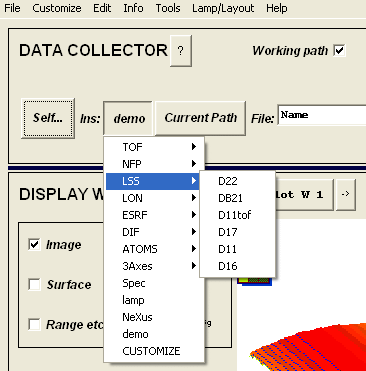
Clicking on the button labelled Data: will cause the label on this button to change to Self:.
At the same time, a number of options will appear to the right of the Self: button.
D17 can be chosen as the working instrument by clicking on the button immediately to the right of Self:. Clicking this button will create a drop menu. D17 will be found in the LSS group of instruments, as can be seen below:
You can now run the D17 macros by typing them in the MANIPULATIONS window.
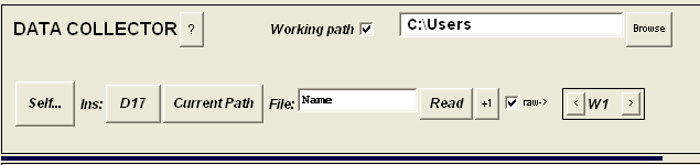
The next button to the right gives LAMP the path to the data files. If you are working from home, you will probably have taken the data with you and put them in a local directory.
To access these files, make sure that the Working Path button is chosen, that correct directory is entered in the field immediately to the right of the button, and that Current Path is selected on the right-most button.
For example, if the D17 data is in C:\Users, the correct LAMP configuration for treating the data with the D17 macros will look like this:
mload
function mload,nums,F12=F12,yaxis=yaxe,norm=norm,mask=maskstring,multiy=multiy,tol=tol
LAMP function to create a workspace from a series of datasets with different flipper states
NECESSARY VARIABLES
nums=EITHER a string with the filenumbers containing the data.
Consecutive files are separated by a colon (:)
Adjacent files are separated by a comma (,)
The string must be enclosed in quotation marks (')
e.g. '90230:90240,90250:90260'
OR an array of numbers
OPTIONAL VARIABLES:
F12 = two element array with flipper states (=0 for off, =1 for on)
e.g. F12=[0,1] is F1=off, F2=on
norm=your choice of normalization, 'time', 'mon', or 'none'
The default (if no scantime is entered) is 'time'
yaxe=your choice for the yaxis, 'san','dan','tra', or 'ran'
The default (if no yaxe is entered) is 'san'
maskstring=your choice of masking the detector, written as a string
The default is no mask
NOTE: The data is NOT normalized to the number of y-pixels in the mask, i.e. circular and elliptical masks will have less weighting away from the centre. Divide by a masked water run to perform this action
multiy=your choice to combine y data with the same SAN/DAN value or not
A string variable, ='av' to combine, 'noav' to leave uncombined
Default is 'av'
tol=a tolerance in y for the y-combination.
Default is 0.004 the appropriate y-axis units
OUTPUT VARIABLES
wout is a workspace with the data of the desired flipper states. If the data is 2D, it will be integrated vertically
The X-axis is given in pixel number
The Y-axis is given as SAN or DAN, user's choice
The Z-axis is the flipper state. If flippers are used, the resulting array will be 3D, each layer containing data of a specific flipper state. If a flipper that is 'off' is labelled with a 0 and a flipper that is 'on' is labelled with a 1, the arrays will be stacked in binary fashion.
e.g. if all four flipper states are used,
The first value of Z will be 00 (flipper1 = 'off', flipper 2 = 'off')
The second value of Z will be 01 (flipper1 = 'off', flipper 2 = 'on')
The third value of Z will be 10 (flipper1 = 'on', flipper 2 = 'off')
The fourth value of Z will be 11 (flipper1 = 'on', flipper 2 = 'on')
The monitor is given as time, monitor, or as unity (for 'none'), user's choice
There is a new array of variables in the 'pv' field. This is a M rows * 8 columns array, where M is the number of steps in the scans. The columns are:
[SAN, DAN, mean date, counting time, monitor, normalization factor, S2W, S3W]
The normalization factor should be multiplied with the data for any further operations (e.g. addition of workspaces) and the errors for the correct propagation of errors
e.g.. type at the LAMP interface:
w1=mload('68263:68300')
This will read all the scans from runs 68263 to 68300. It will sort the data by flipper state, integrate vertically over the detector (if necessary), normalise the data to time, average all data at the same SAN and return a 2- or 3D array (depending on how many flipper states were used) of the data with x-pixel vs. SAN.
NOTE: If more than one flipper state was used, the number of measurements for each flipper state must be EQUIVALENT! If they are not, the number of rows in the data arrays will not match and mload will complain.
w1=mload(68263+indgen(37),F12=[0,0])
Similar to above, but will return a 2D array containing only the data with both flippers off.
w1=mload('68263:68300',F12=[0,0],yaxis='san',norm='time',mask='box,[190,200,63,222]',multiy='av')
Similar to above, with a box mask applied to the 2D detector before integrating over the vertical direction.
maskme
function maskme,maskproc,win,datp=datp
LAMP function to mask the unwanted points from a workspace
NECESSARY VARIABLES
maskproc=a string with the mask procedure and relevant parameters
The available mask procedures are:
box: needs a 2- or 4-element array to define the box
for a 2 element array, the limits are [xmin,xmax]
for a 4 element array, the limits are [xmin,xmax,ymin,ymax]
circle: needs a 3-element array with centreX, centreY, radius
ellipse:needs a 4-element array with Xlocus, Ylocus, centreX, centreY
win=input workspace
OPTIONAL VARIABLES
datp = the data structure for the workspace
If unspecified, the program will take the data structure from the workspace
e.g. type at lamp interface:
w2=maskme('box,[190,200,63,222]',w1)
d17_waterdef
function d17_waterdef,nums,dims=dims,mask=maskstring
LAMP function to load in a water run, mask it and normalize it
NECESSARY INPUT:
nums=a string with the filenumbers containing the data.
Consecutive files are separated by a greater than (>)
Add non-consecutive files using a plus (+)
The string must be enclosed in quotation marks (')
e.g. '90230>90240+90250>90260'
OPTIONAL INPUT:
dims=the dimension of the output workspace. Can be 1 or 2.
If nothing is specified, the output workspace will have the same dimensions as the input data
maskstring=your choice of masking the detector, written as a string
The default is no mask
e.g. type at LAMP interface:
w1=d17_waterdef('90230+90250',dims=1,mask='box,[190,200,63,222]')
d17_waternorm
function d17_waternorm,win,water
LAMP function to normalize a workspace by the water file
Designed to run with a 1D array of water (loaded by, e.g., d17_waterdef)
and with data that has been integrated vertically
NECESSARY VARIABLES:
win=the input workspace
water=the workspace with the water data
e.g. w3=d17_waternorm(w2,w1)
d17_polcorr
function d17_polcorr,win,phi=phi,F1=F1,F2=F2,p1=p1,p2=p2
LAMP function to take up to four workspaces, one for each flipper state, and to correct for the polarizing inefficiencies.
The corrections are based on the equations in Wildes, Rev. Sci. Instrum., 70 (1999) 4241
NECESSARY INPUT:
win=input workspace. This can be a 4 rows x N columns matrix, where N is the number of 2 theta values. The order of the rows *must* be (from the top) I00, I01, I10, I11. It is assumed that each column gives the values of I measured at *the same* position in theta
'mload' will automatically create an array of the right dimensions, and in the right order.
You can create such a matrix from four 1d datasets using the aw_four1d2one2d function OR, it can be a 2 rows x N columns matrix for those measurements without an analyser (i.e. for 'asymmetry'). In this case, the order of the rows *must* be (from the top) I0, I1
SEMI-NECESSARY INPUT:
All this input is in the form of a two-element array,
the first number is the value of the parameter
the second number is its error
The program aw_polcalc returns the values in the right format
Depending on the type of measurement, you must include some combination of the following:
p1=inefficiency of the polarizer (between 0 and 1)
p2=inefficiency of the analyzer (between 0 and 1)
F1=inefficiency of the first flipper (between 0 and 1)
F2=inefficiency of the second flipper (between 0 and 1)
phi=p1+p2-2*p1*p2 (between 0 and 1)
NOTE: If you enter p1 and/or p2, the program will IGNORE phi!
OUTPUT:
The workspace will be either a 4 rows x N columns matrix,
the order of the rows will be (from the top)
SIGMA(++),SIGMA(+-),SIGMA( +),SIGMA(--)
Or the workspace will be a 2 rows x N columns matrix,
the order of the rows will be (from the top) SIGMA(+),SIGMA(-)
e.g. type at LAMP interface
w6=d17_polcorr(w5,F1=[0.007,0.0008],F2=[0.005,0.0008],p1=[0.05,0.002],p2=[0.011,0.002])
(good for ferro and ferrimagnets)
w6=d17_polcorr(w5,F1=[0.007,0.0008],F2=[0.005,0.0008],phi=[0.05,0.002])
(good for antiferro and paramagnets)
w6=d17_polcorr(w5,F1=[0.007,0.0008],p1=[0.05,0.002])
(good for spin asymmetry)
d17_polcalc
pro d17_polcalc,main,maskm=maskm,ferro=ferro,maskf=maskf,phi,F1,F2,p1,p2
LAMP procedure to calculate the inefficiencies of the polarizing elements based on a series of scans with different flipper states
The corrections are based on the equations in:
Wildes, Rev. Sci. Instrum., 70 (1999) 4241
NECESSARY VARIABLES:
main = Can be either:
i) an array of eight numbers corresponding to the integrated intensities
measured for the main beam OR a reflection from a non-polarizing
sample (e.g. silicon), with their errors.
The format of the numbers is as follows:
[I00,e(00),I10,e(10),I11,e(11),I01,e(01)]
ii) a string with files containing the same information
Syntax for the string is the same as for MLOAD
OPTIONAL VARIABLES:
ferro = Can be either:
i) an array of four numbers corresponding to the integrated intensities
measured for the reflection from a ferromagnetic sample, with their errors
The format of the numbers is as follows:
[I00,e(00),I10,e(10),I11,e(11),I01,e(01)]
ii) a string with files containing the same information
Syntax for the string is the same as for MLOAD
maskm = mask string for "main" files - useful if files are input
Syntax for the string is the same as for MASKME
maskf = mask string for "ferro" files - useful if files are input
Syntax for the string is the same as for MASKME
OUTPUTS:
All the outputs are two component arrays, the first element is the value and the second is the error
phi=a combination of the efficiencies of the polarizer and the analyser
F1=the efficiency of the 1st flipper
F2=the efficiency of the 2nd flipper
p1=the efficiency of the polarizer (can only be determined if ferro is included)
p2=the efficiency of the analyser (can only be determined if ferro is included)
e.g. type at the LAMP interface
d17_polcalc,[2206,10.2,20,2.1,2110,9.5,40,3.1],ferro=[1104,5.2,20,2.1,100,10.0,10,3.1],phi,F1,F2,p1,p2
d17_polcalc,'81624:81627',maskm='box,[63,73,11,51]'
d17_he3calc
pro d17_he3calc,refl,main=main,water=water,mask=maskstring,time,phi,f1,f2,trans
LAMP procedure to take a standard 7-run measurement of the four flipper states for a He3 calibration and return the calculated phi, f1 and f2 for the mean time of the measurements. The calculation is from the equations in Wildes, Rev. Sci. Instrum., 70 (1999) 4241
NECESSARY VARIABLES:
refl=a string with the first and last of the 7 files, separated by a colon
OPTIONAL VARIABLES:
main=a string with the numbers for a measurement of the main beam, with an empty cell
water=the number of the workspace with the (masked) water file in it.
The data will be divided by this workspace if it exists
maskstring=your choice of masking the detector, written as a string
The default is no mask
OUTPUT VARIABLES:
time=the mean time for the measurement. The values for phi,f1,f2 and trans correspond
to this time
phi=the combined polarizer/analyzer inefficiency
f1=the first flipper inefficiency
f2=the second flipper inefficiency
trans=the transmission of the cell. This is only output if 'main' is specified
e.g. d17_he3calc,'90230:90236',main='90201',water=1,mask='box,[190,200,63,222]',time,phi,f1,f2,trans
d17_he3corr
function d17_he3corr,win,params,tol=tol
LAMP function to correct polarization analysis data taken with the He3 filter
NECESSARY VARIABLES:
win=workspace with the data, must have the four polarization states as
[[I00],[I01],[I10],[I11]]
params=the fitted parameters to phi and trans
This can be a 1 or 2D array,
the second row in a 2D array is the error on the parameter
params[0]=initial time for filter (t0)
params[1]=initial polarization of 3He gas (P0He)
params[2]=decay time of cell (t1)
params[3]=polarizer inefficiency (p1)
params[4]=gas pressure ([3He])
params[5]=wavelength (lambda)
params[6]=first flipper efficiency (f1)
params[7]=second flipper efficiency (f2)
Cell thickness is fixed at 10 cm
OPTIONAL VARIABLES:
tol=the tolerance in the time for the measurement in seconds.
The correction requires a time of measurement for the 4 flipper states
This is taken as the average time of measurement.
There will be some variation on the calculated average, normally +/- a second or two
If you have problem, tol=2 should cover this and allow a proper correction to be made
If the data falls outside this tolerance, an error message will be sent
The default tolerance is 1e-7 seconds.
e.g. w5=d17_he3corr(w4,p,tol=2)
d17_he3calibrate
function d17_he3calibrate,calfiles,main=main,water=water,mask=maskstring,F1=FF1,F2=FF2
LAMP function to create a workspace with the values of phi,F1,F2 and transmission as a function of time.
The function uses d17_he3calc to calculate phi, F1 and F2,
It then estimates the mean F1 and F2 (which are time-independent)
It then recalculates phi (the only time-dependent quantity)
The output has 7 rows:
Row 1 = phi, calculated for each He3 calibration
Row 2 = F1, calculated for each He3 calibration
Row 3 = F2, calculated for each He3 calibration
Row 4 = transmission, calculated for each He3 calibration
Row 5 = phi calculated from the mean value of F1 below
OR, using the optional F1 and/or F2 if specified
Row 6 = the mean F1 for all the He3 calibration files
Row 7 = the mean F2 for all the He3 calibration files
The errors have also been estimated assuming Poissonian statistics
NECESSARY VARIABLES:
calfiles=a string with ALL the 3He calibration runs included
The first and last file for each calibration scan must be
separated by a colon (:)
Separate calibration scans must be separated by a comma (,)
OPTIONAL VARIABLES:
main=a string with the numbers for a measurement of the main beam, with an empty cell
water=the number of the workspace with the (masked) water file in it.
The data will be divided by this workspace if it exists
maskstring=your choice of masking the detector, written as a string. See maskme for more information on syntax.
The default is no mask
FF1 = a two element array with the first flipper efficiency and its error
Specify this if you want to force F1 to a value
FF2 = a two element array with the second flipper efficiency and its error
Specify this if you want to force F2 to a value
e.g. w1=d17_he3calibrate('97087:97093,97339:97345,97591:97597',main='90201',water=1,mask='box,[190,200,63,222]')
d17_he3fit
pro d17_he3fit,win,pin,pout,yout,PFIX=pfix,LIMITS=lims,DSEL=dsel,CROSS=cross
LAMP procedure to fit the 3He data to calculate the
polarization decay constants.
NECESSARY INPUT:
win=the workspace with the values of phi.
calculated using aw_he3calibrate
pin=the input parameters:
pin(0) = definition of time t=0 (by 'julday')
pin(1) = initial polarization of the He3 gas (%)
pin(2) = the time constant for decay (hours)
pin(3) = the inefficiency of the polarizer
pin(4) = the pressure of the gas (bar)
pin(5) = the wavelength (Angstrom)
OPTIONAL INPUT
pfix=a 6-element array showing which of pin are fixed and which are free
A value of zero is free, a value of one is fixed
limits=a 2 column by 6 row array with the upper and lower limits
for each parameter. Set values to -1 for no limit
dsel=a 2row array with the same number of columns as data points
This parameter can be set to deselect data points
The top row refers to polarization data, while the bottom refers to the transmission
A value of 0 means that the corresponding data point is DESELECTED
Any other value and the point is SELECTED.
Default is (of course) all data points selected
cross=0 if the 3He is polarized in the SAME direction as the monochromator
=1 if the 3He is polarized OPPOSITE to the monochromator
Default is cross=0
OUTPUT:
pout=the output parameters with errors as a 2 column array:
pout(0) = definition of time t=0 (by 'julday')
pout(1) = initial polarization of the He3 gas (%)
pout(2) = the time constant for decay (hours)
pout(3) = the inefficiency of the polarizer
pout(4) = the pressure of the gas (bar)
pout(5) = the wavelength (Angstrom)
pout(6) = the first flipper efficiency
pout(7) = the second flipper efficiency
yout=the values of phi and trans as a function of time
Example:
d17_he3fit,w2,[julday(8,3,2004,14,15,00),0.6,150,0.013,0.6,5.3],pout,w11, $
PFIX=[0,0,0,1,0,1], $
LIMITS=[[-1,min(x2)],[0.5,0.65],[100,200],[0,0.02],[0.5,0.7],[-1,-1]]
d17_xyconvert
FUNCTION d17_xyconvert,win,oaxes,mainbeam,lambda=lambda,sanoff=sanoff, datp=datp
LAMP function to convert a workspace's coordinates for the (x,y) pixels to numbers with physical meaning.
Works for both monochromatic and TOF data sets
For monochromatic data, the input workspace must have (comes automatically when created using mload):
x-pixel on the x-axis
SAN or DAN on the y-axis
Monochromatic data may be 3D
For TOF data, the input workspace must have (comes automatically when D17 TOF data is loaded in to LAMP):
x-pixel on the x-axis
wavelength on the y-axis
TOF data must be 2D
NECESSARY INPUT:
win=input workspace
oaxes=the output axes, put as a string
Allowable options are:
'qxqz' = qx (x-axis) vs. qz (y-axis)
'pipf' = pi-pf (x-axis) vs. pi+pf (y-axis)
the above options are available for TOF and monochromatic data sets
'tito' = theta out (x-axis) vs. theta in (y-axis)
'stth' = two theta (x-axis) vs san (y-axis)
the above options are only available for monochromatic data sets
'ltth' = two theta (x-axis) vs wavelength (y-axis)
the above option is only available for TOF datasets
mainbeam=data file for the main beam, used to calibrate twotheta
OPTIONAL INPUT:
lambda=wavelength settings. This has two possibilities:
Monochromator data: this is the actual wavelength, a single number.
This should be stored with the data, but you have the
option here of forcing it to another value
e.g. lambda = 5.325
TOF data: this is a two element array with the minimum and maximum
wavelengths for the calculation
e,g. lambda = [2,20] (this happens to be the default)
sanoff=an offset in SAN, which can exist if the sample angle calibration
is out. This value is SUBTRACTED from the instrument-stored value
of SAN to find the correct value for theta_in
For an attempt to automatically find sanoff, use sanoff='auto'
Otherwise, equate sanoff to a number (default is 0)
datp=a structured array, generated in LAMP, that carries the workspace information with it. Only necessary if d17_xyconvert is called from within another subroutine
e.g. type at LAMP interface:
w2=d17_xyconvert(w1,'qxqz',97936,sanoff='auto')
d17_xspec
FUNCTION d17_xspec,win,spix,bkg=bkg,method=method,mbeam=mbeam,snorm=snorm,xaxis=xaxis,lambda=lambda,sanoff=sanoff
LAMP function to extract the specular intensity from a workspace.
It also (correctly) calculates the errors and weights by the number of pixels
in each range
NECESSARY VARIABLES:
win = the input workspace, loaded through mload
spix = two element array with the left and right pixels that limit the
width of the specular ridge
OPTIONAL VARIABLES:
bkg = two column times n row element array that define the background pixels
method = a string stating the type of background subtraction you would like to do.
May also involve rebinning the data.
The choices are:
'smpl' = keeps the data in (x-pixel, san) space,
integrates the counts within a certain range of x-pixels for each row,
and subtracts backgrounds calculated by row from the data .
This is the default, and is useful for narrow, well-defined specular reflectivity with no significant off-specular.
'tth' = Converts the data in (twotheta, san) space,
assumes that theta_in = twotheta/2 and calculates Qz based on this,
but subtracts backgrounds calculated by row from the data.
This is useful for messy reflectivity peaks with no significant off-specular
(e.g. bent and/or faceted substrates)
This option will rebin the data in Qz.
'q' = converts the data in to (pi-pf, pi+pf) space,
interpolates the data on to the central pixel,
and subtracts backgounds interpolated on to the same Qz.
This is useful for samples with large off-specular
(e.g. rough multilayers)
This option will rebin the data in Qz.
mbeam = the number with a main beam measurement.
This is a NECESSARY VARIABLE if 'tth' or 'q' are chosen for the method
snorm = normalization to slit sizes. A string input is required.
Two options are possible:
'none'= no normalization (default choice)
'q' = divides the intensities by Q (equivalent to dividing by sin(theta))
's2' = divides the intensities by S2W
's2q' = divides the intensities by S2W*Q (equivalent to dividing by sin(theta))
's2s3'= divides by S2W*S3W
xaxis = a choice of the final x-axis values
You may choose the x-axis in Qz (xaxis = 'q') (default choice)
or theta_in (xaxis='san')
lambda = the wavelength. If unspecified, the wavelength will be taken from the data parameters
sanoff = an offset in the sample angle in degrees.
This will be ADDED to the recorded sample angle
You may specify 'auto' here for the program to guess for you
Default is sanoff=0 for 'smpl', and is 'auto' for 'tth' and 'q'
OUTPUT VARIABLES
wout is the workspace containing the specular intensity, background subtracted,
with the x-axis = the y axis for win
e.g. type at LAMP interface:
w2=d17_xspec(w1,[60,85])
(extracts the data between x-pixels 60 and 85 and integrates as a function of SAN)
w2=d17_xspec(w1,[60,85],bkg=[[50,59],[86,90]])
(as above, also integrates between 50-59 and 86-90 and takes this as the background)
w2=d17_xspec(w1,[60,85],bkg=[11,59],method='tth',mbeam=22189,xaxis='q',lambda=5.513,sanoff='auto')
(the full monty!)
d17_2dnorm
d17_2dnrom is a macro that normalizes 2-dimensional TOF vs x-pixel D17 files to a direct beam measurment.
There are several subroutines available. The simplest one just divides the 2D image by a direct beam spectrum by interpolating the direct beam wavelengths to the reflected beam measurement:
e.g. w4=d17_2dnorm(w1,w3,lrange=[2,27]), where w1 is the reflected beam 2D image, w3 is the direct beam 1D spectrum and lrange fixes the wavelength range to be considered.
d17_2dnorm_mask: A more elaborate routine, which needs only the run-numbers as input and automatically makes the direct beam projection and it also has the option to subtract background from the reflectied and/or direct beam measurements:
; NECESSARY VARIABLES:
; nums(string)=the input run(s). Multiple runs can be connected by colon (: = consecutive), comma (,) or plus (+) for adding individual
; mainbeam(string)= run(s) with the main beam data
;
; OPTIONAL VARIABLES:
; background(string)=a background run to subtract from the data
; lrange = a two-element array with the maximum and minimum values of lambda
; norm = a string to define the normalization of the data (default is time)
; mask = define the foreground for the main beam measurement. Only box allowed at the moment without restricting the wavelength. See "maskme" for further details.
; backmask = mask the background
; 1) if background is not specified, but backmask is given: region will be taken from input data, integrated over wavelength and subtracted from data
; 2) if background is not specified and no mask is given, no background will be subtracted
; 3) if background is specified, but no backmask is given, the background run will be subtracted in 2D without integration
; 4) if background is specified and a backmask is given, the background will be integrated over mask
; mbmask = mask the background of direct beam
;
;e.g.
;w1=d17_2dnorm_mask('370339','370340',background='370341',lrange=[1.6,27],norm=time,mask='box,[171,181]',backmask='box,[50,230]',mbmask='box,[140,166]')
, where 370339 is the reflected beam measurement, 370340 is the direct beam run number and 370341 is the background measurment.
slitwit
slitwit is a GUI macro that will allow you to calculate the beam footprint on your sample and the beam divergence (FWHM). Just type slitwit in the LAMP command line and execute it. A self-explaining GUI will appear.