T-Gradient Monochromator
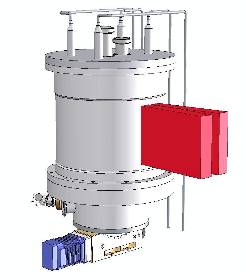
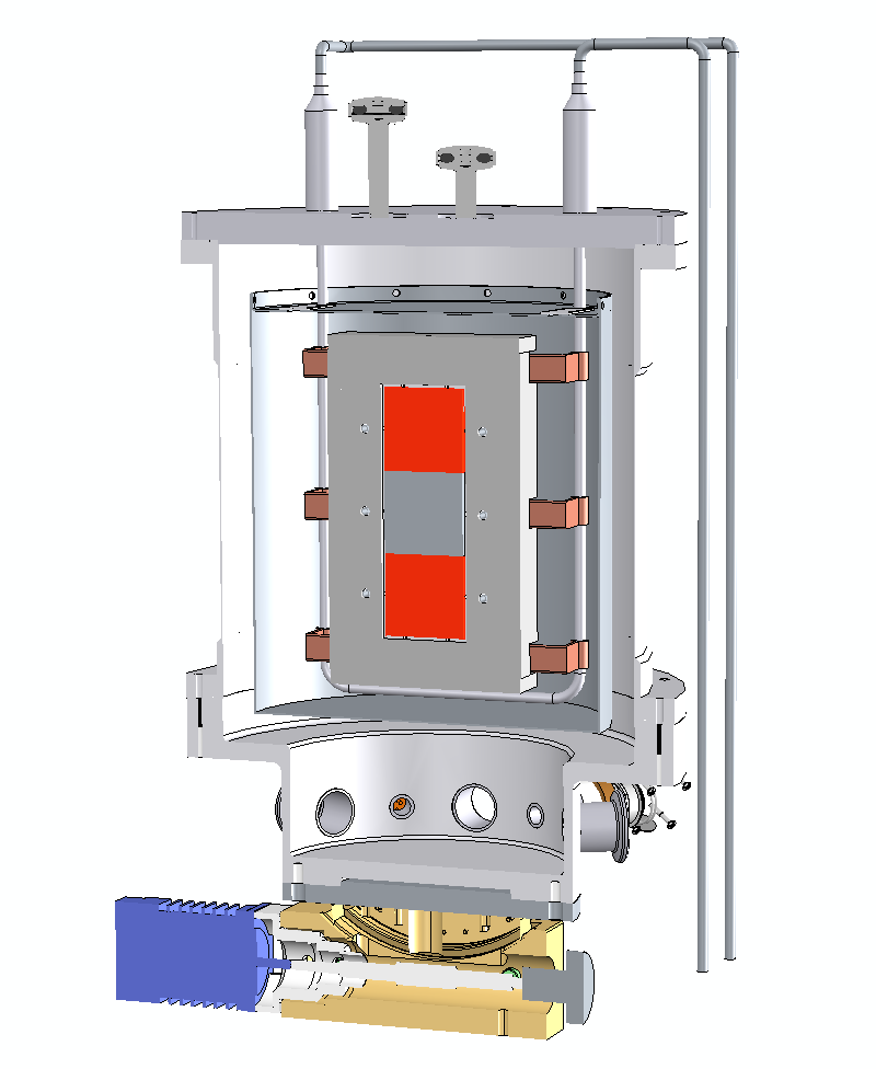
The cryofurnace hosting the IN13 monochromator regulates the temperature of CaF2 crystals between -200°C and +200°C to scan the lattice parameter and thereby change the energy of the incident beam. For some measurements, the highest energy resolution is not necessary and the neutron flux at the sample can be increased by enlarging the distribution of d-spacings in the monochromator crystals. This is done by creating a thermal gradient in the direction parallel to the incident beam.
The average temperature of the CaF2 crystals is controlled by two independent aluminium faces pressed against the crystal faces. Each face is thermally anchored to a liquid nitrogen loop and heaters. The nitrogen flow-rate is regulated by a mass-flow controller and heaters are powered with standard power supplied. The temperatures of the two faces are controlled by providing two setpoints: T and ∆T. A logic process controller (Schneider M251) determines the appropriate flow-rates and regulates the heaters so that one face is stabilised at the temperature T while the other at T + ∆T.
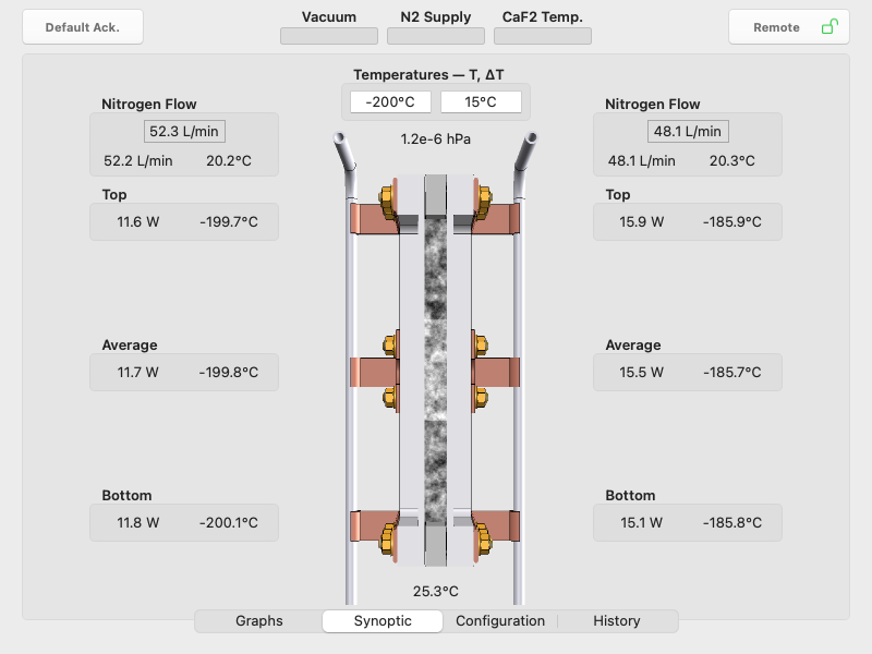
The graphical user interface of the humain machine interface (Schenider HMI Harmony GTU) proposes 4 screens selected from a tab bar:
- Graphs: Temperature and vacuum pressure evolution of the faces
- Synoptic: schematic assembly of the crystals pressed by the two faces displaying all parameters
- Configuration: for setting the mass-flow rates and max heating powers applied linearily on temperature ranges
- History: Logs of all actions and errors since the beginning of its use
At the top of the screens, indicators are permanently displayed to report potential alarms and defaults. Data are collected and stored in a flash memory. The cooling and heating of the CaF2 crystals is automatic.
Full remote control
Computer control via Ethernet is provided for monitoring all parameters and start or stop the cooling. The communications are based on the Modbus communications protocol which is an industrial standard. We provide a Modbus XOP and routines in a Procedure file for controlling Modbus-TCP devices with Igor Pro.
PLC Registers (Schneider M251 Logic Controller)
| Description | Read | Write | Address |
|---|---|---|---|
T-face regulation temperature in °C (top) |
X |
- |
40 001 |
T-face regulation temperature in °C (bottom) |
X |
- |
40 003 |
∆T-face regulation temperature in °C (top) |
X |
- |
40 005 |
∆T-face regulation temperature in °C (bottom) |
X |
- |
40 007 |
Analysers temperature in °C |
X |
- |
40 009 |
Indium seal temperature in °C (bottom) |
X |
- |
40 011 |
Vacuum pressure in hPa |
X |
- |
40 013 |
Temperature setpoint in °C (i.e. T-face setpoint) |
X |
X |
40 015 |
∆T temperature difference setpoint in °C (∆T-face setpoint = T + ∆T) |
X |
X |
40 017 |
T-face nitrogen flow-rate setpoint in L/min |
X |
- |
40 019 |
∆T-face nitrogen flow-rate setpoint in L/min |
X |
- |
40 021 |
T-face mass-flow controller temperature in °C |
X |
- |
40 023 |
∆T-face mass-flow controller temperature in °C |
X |
- |
40 025 |
NOMAD tolerance in °C |
X |
X |
40 027 |
T-face averaged temperature in °C |
X |
- |
40 029 |
∆T-face averaged temperature in °C |
X |
- |
40 031 |
Averaged temperature in °C |
X |
- |
40 033 |
Firmware version |
X |
- |
40 035 |
Alarm — Insufficient liquid N2 supply |
X |
- |
40 201.0 |
Alarm — Insufficient vacuum |
X |
- |
40 201.1 |
Alarm — CaF2 temperature too high |
X |
- |
40 201.2 |
Alarm — Mass-flow Controller #1 |
X |
- |
40 201.3 |
Alarm — Mass-flow Controller #2 |
X |
- |
40 201.4 |
Alarm — Mass-flow controller temperature out of range |
X |
- |
40 201.5 |
Fault — Insufficient liquid N2 supply |
X |
- |
40 201.6 |
Fault — Insufficient vacuum |
X |
- |
40 201.7 |
Fault— CaF2 temperature too high |
X |
- |
40 201.8 |
Fault — Mass-flow Controller #1 |
X |
- |
40 201.9 |
Fault — Mass-flow Controller #2 |
X |
- |
40 201.10 |
Fault — Mass-flow controller temperature out of range |
X |
- |
40 201.11 |
Fault — Top indium seal too hot |
X |
- |
40 201.12 |
Fault — Bottom indium seal too hot |
X |
- |
40 201.13 |
Equipment status — Idle bit |
X |
- |
40 202.1 |
Equipment status — Running bit |
X |
- |
40 202.2 |
Equipment status — Local (0)/Remote bit (1) |
X |
X |
40 202.3 |
Equipment status — Default acknowledgement bit |
X |
X |
40 202.4 |
Firmware Updates
Please find below the release history and some instructions for updating the firmware.
Release History
- 1.00 - Initial release for prototype testing
- 2.00 - First release installed on IN13 in March 2023