Magnetic Forces Monitor
Magnetic Forces Measurement Unit

For safety reasons, the magnetic forces that appear on an instrument when using a cryomagnet are measured before using a new system or after a modification has been made to the instrument. These measurements are mandatory. The conditions in which a cryomagnet can be used are determined from these measurements and reported in the Safety section.
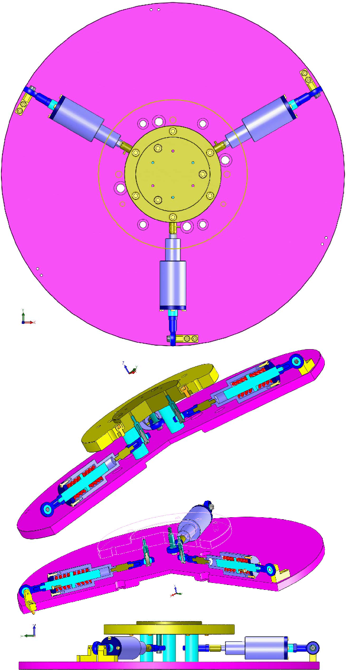
The vertical force is simply obtained from a dynanometer installed on the crane. The horizontal force is measured with 3 piezo sensors oriented at 120° and attached to both the cryomagnet and the sample table. The magnitude and direction of this horizontal force are calculated and displayed on a Eurotherm controller.
Please click on the left menu items to obtain more information on the utilization of the electronics, its specifications and a history of the revisions of the firmware.
Instruction Manual
The ILL magnetic forces monitor has been carefully designed and manufactured to provide hours of trouble-free service. Its user interface has also been designed to simplify its operation as far as possible. The monitor displays the forces measured by each sensor, the magnitude of the horizontal force and its orientation relative to the sensor #1. A high alarm can be set to indicate when stopping the energization of the magnet.
The forces are measured by 3 identical piezo sensors mounted in the horizontal plane at 120° from each other. The mechanics is designed so that it is compatible with the sample tables of all the instruments and all cryomagnets. To measure the forces, the system is clamped to the ring of the magnet and to the sample table, with the cryomagnet suspended from a crane equipped with a dynanometer.

Operation
The monitor reports the readings of the 3 sensors. It also calculates the magnitude of the force and its orientation relative to the direction of the sensor #1. An alarm is activated if the force exceeds the value stored in the monitor (high-force alarm).
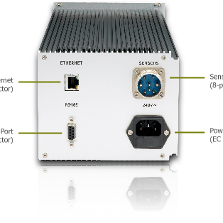
Interfacing
The monitor can be remotely controlled through a RS485 or Ethernet link using the Modbus communication protocol (public function code 3).
Technical Specifications
The ILL magnetic forces monitor is currently supplied with the version 1.02 of the soft-wired program installed and preset with the specifications of our piezo sensors. Remote control is performed using the registers listed below.
Firmware Update
The latest release 1.02 improves the user interface and the management of the pages.
Size and Weight
The monitor fits within a 19"/3U chassis.
- Height: 129 mm (5.1 inches)
- Width: 143 mm (5.6 inches)
- Depth: 355 mm (14 inches)
- Weight: 2.63 kg (5.8 pounds)
Modbus registers
| Description | Min | Max | Address |
|---|---|---|---|
Sensor #1 value in daN |
-100 |
+100 |
360 |
Sensor #2 value in daN |
-100 |
+100 |
364 |
Sensor #3 value in daN |
-100 |
+100 |
290 |
Magnitude of the force in daN |
0 |
100 |
4782 |
Orientation of the force in degrees |
0 |
359 |
4968 |
High force limit in daN |
0 |
100 |
10241 |
Alarm error |
0 |
1 |
10249 |
Firmware version |
1 |
10 |
4977 |
Electrical and operating requirements
Contact us if you need a 100V AC / 60 Hz unit.
- Line voltage: 240V AC
- Frequency: 50Hz
- Operating temperature: 10 to 35°C (50 to 95 °F)
- Storage temperature: -24 to 45°C (-13 to 113 °F)
- Relative humidity: 5 to 85% noncondensing
Firmware Updates
Please find below the release history and some instructions for updating the firmware. To obtain the most recent release of the firmware, please contact us.
Release History
- 1.00 - Initial release.
- 1.01 - Addition of the calculation of the orientation relative to the direction #1.
- 1.02 - Improvements to the user interface and the management of the pages.
Instructions for updating the controller
- Install iTools (available here),
- Connect the controller to the computer with an Ethernet cable,
- Configure the TCP/IP parameters of the computer:
- Select the Connection panel and click on TCP/IP Properties,
- Enter the fixed IP address 192.168.1.1,
- Enter the subnet mask 255.255.255.0,
- Enter the gateway address 192.168.1.0,
- Launch iTools and open the OPC Server window,
- Open the "Scan for TCP hosts..." panel from the Add/New TCP Network Port menu command,
- Enter the TCP/IP address 192.168.1.205 (standard address of the magnetic forces monitor),
- Launch the scan and stop it once the controller is detected,
- Reduce the OPC Server window (do not close it!),
- Click on the Scan icon of the main iTools toolbar and launch a search for connected instruments,
- After the scan, click on the Load icon of the main toolbar, select the new firmware and launch the update.