Clip
CLIP ("Cologne Laue Indexation Program") is written by Olaf Schumann.
It may be freely downloaded at https://clip4.sourceforge.net.
Click here for the CLIP manual.
CLIP requires image files with clearly visible Laue spots. CLIP can read image files in formats *.bmp, *.png, *.gif, *.jpg, *.jpeg, and *.tiff.
Raw images directly from NOMAD are likely to need some treatment, such as despeckling and brightness/contrast adjustments. CLIP allows for some image processing of *.tiff files. You may also like to use ImageJ for more sophisticated processing.
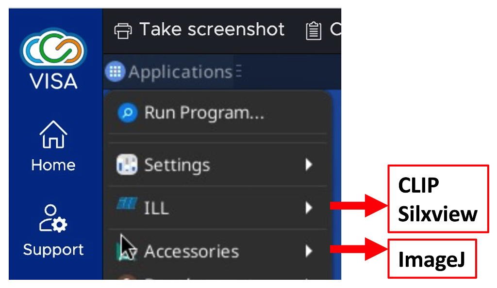
CLIP is available from a VISA instance. It can be installed by following the menu chain:
Applications : ILL : CLIP
Two versions are available:
- Clip (4b2) is a base version of CLIP
- Clip (4.3.0 beta) also allows for some image processing,
The Clip (4.3.0 beta) version is usually a good choice.
CLIP cannot read the raw NEXUS files!
Usable CLIP data will be found in the processed subdirectory under your proposal number.
After logging in to NOMAD and selecting the correct proposal number, your data can be loaded from:
~/MyData/byInstrument/orient/exp-<proposal>_<cycle>_orient/processed
where:
<proposal> is your proposal number
<cycle> is the cycle number (e.g. 261 is the first cycle from 2026).
If using internalUse as the proposal number, the data are stored in the directory:
/net4/serdon/illdata/<cycle>/orient/internalUse/processed
If you are using data from the current cycle, you can also find the internalUse data in:
/net4/serdon/illdata/data/orient/internalUse/processed
CLIP Tutorial
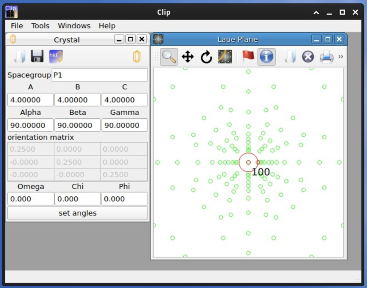
Starting CLIP will open a window on the monitor. This is the CLIP desktop.
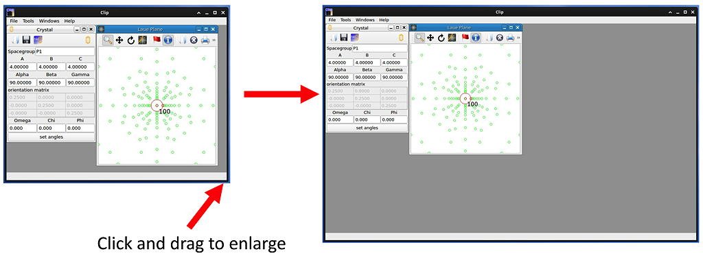
The desktop can be made larger by clicking and dragging the bottom right-hand corner.
Give yourself some space! You're going to need it.
The CLIP desktop opens with two windows:
- the Crystal window
- the Laue Plane window
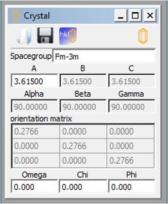
Select the Crystal sub-window.
Enter the correct space group and lattice parameters.
The orientation matrix and values for Omega, Chi and Phi are unimportant for the moment.
If the unit cell window is closed, a new one may be opened from the File : New Crystal menu option.
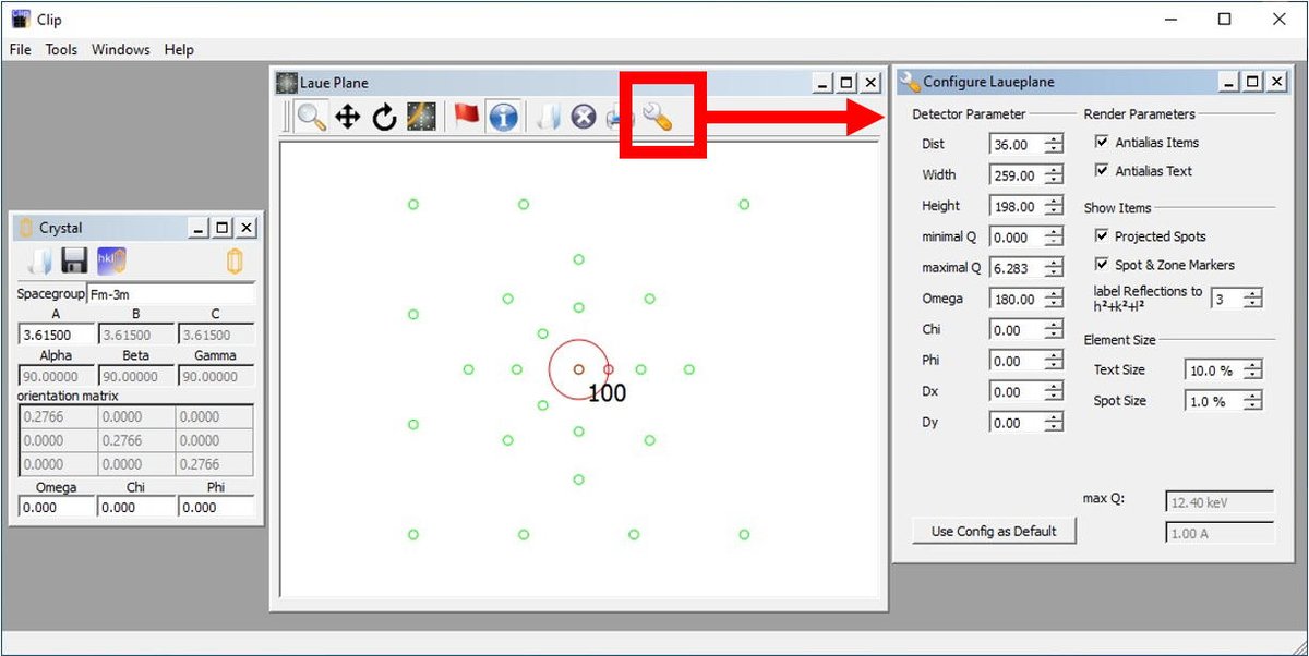
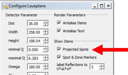
Open the Configure Laueplane window by clicking the 'spanner' icon in the Laue Plane window.
The detector Width = 240 and Height = 190.
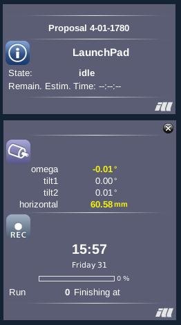
Pay particular attention to Dist, which is the sample-detector distance. The correct value is given by the Horizontal motor axis in NOMAD.
If the Laue Plane window is closed, a new one may be opened from the File : New Laue Plane menu option.
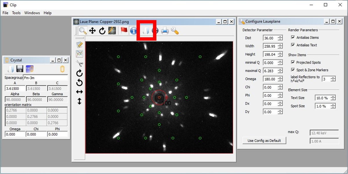
This is done by clicking the 'Book' icon in the Laue Plane window.
Note the allowed image formats listed at the top of this page. CLIP cannot read a raw NEXUS file.
CLIP (4.3.0 beta) has some image processing capabilities.
- These capabilities only work on TIFF images.
- CLIP cannot despeckle images.
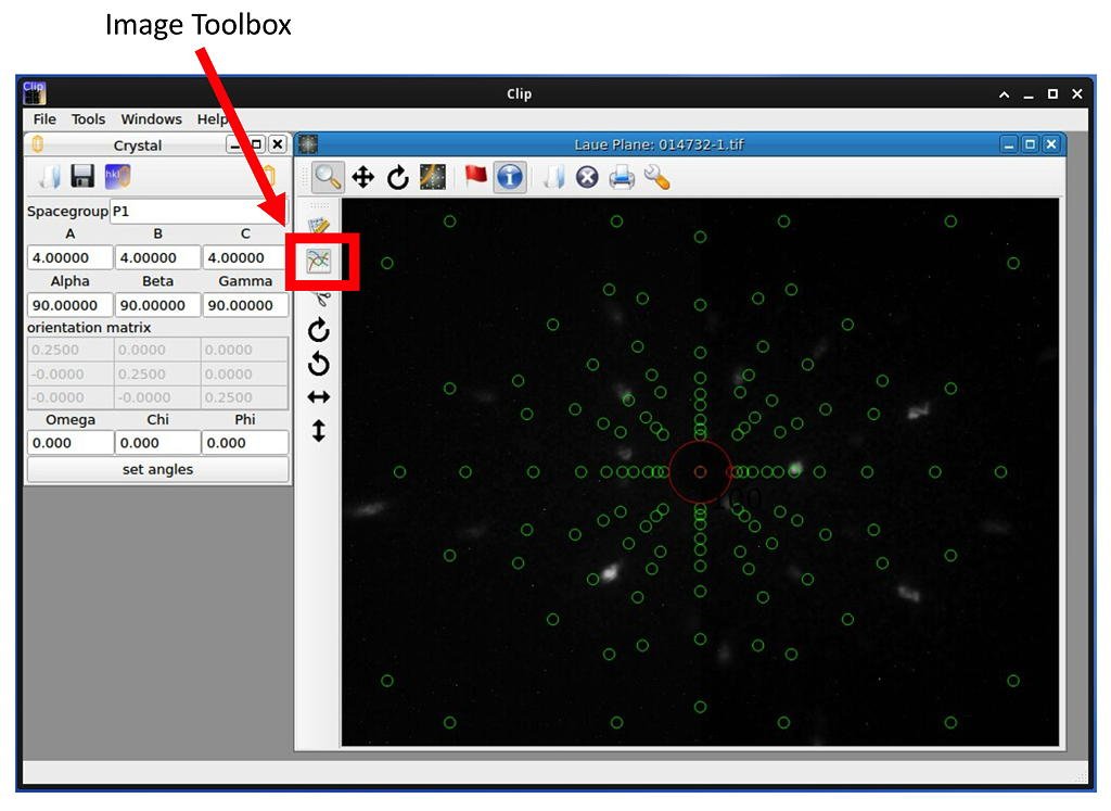
Loading data will result in a menu bar appearing to the left of the Laue Plane window. You can access the Image Toolbox window by clicking the button in the new menu bar.
The spectral distribution can be adjusted from the Contrast tab on the Image Toolbox window. Click-and-drag to adjust the image to your liking.
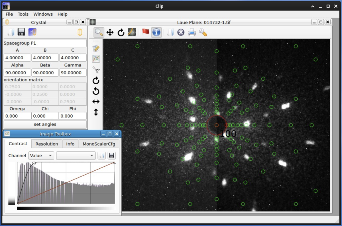
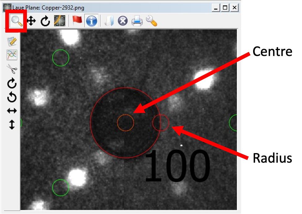
The main beam is defined in the Laue Plane image with a red circle.
The circle may be moved by clicking-and-dragging the smaller circle in its centre.
The circle radius may be changed by clicking-and-dragging the smaller circle on its circumference.
The image may be zoomed by using the magnifying glass icon in the Laue Plane window. Right-click to reset the zoom.
Use the Zone tool in the Laue Plane window to define some Laue zones.
With the tool active, click on a peak position and drag to another peak on the same trajectory.
A line will appear on the image.
The line contains two small red circles. The line can be modified by clicking and dragging one of the circles, or deleted by right-clicking on a circle.
Select at least three zones before attempting to index.
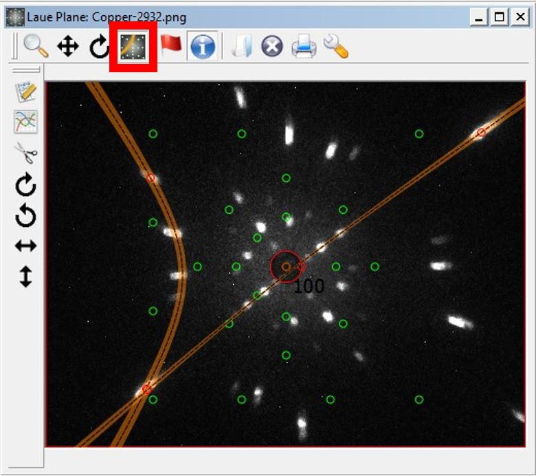
Hot tip: The green circles show the projected spots. You might find them distracting when choosing the Laue zones. You can toggle their visibility from the Configure Laueplane window.
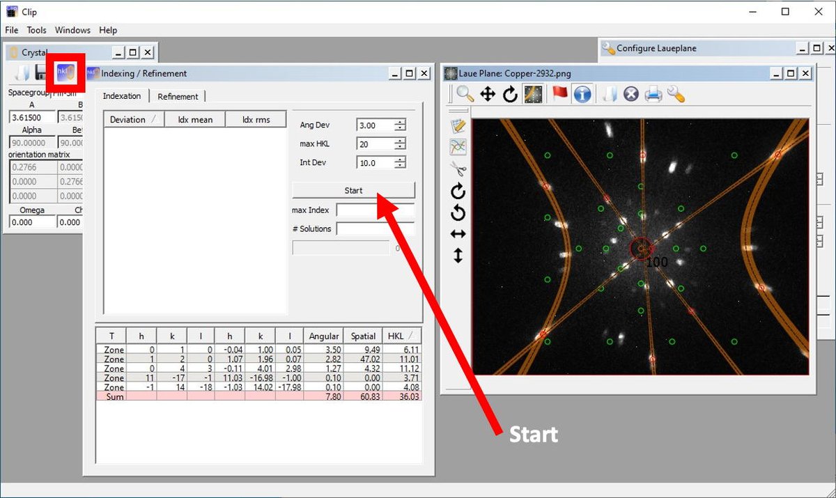
Open the Indexing / Refinement tool by clicking on the hkl icon in the Crystal window.
The window has a Start button. Click this button to start and stop the indexing.
CLIP will not stop indexing on its own. If it runs for too long, CLIP will run out of memory and will crash.
YOU must be the one to stop the indexing. Letting CLIP run the indexing for ~1 - 3 seconds is about right.
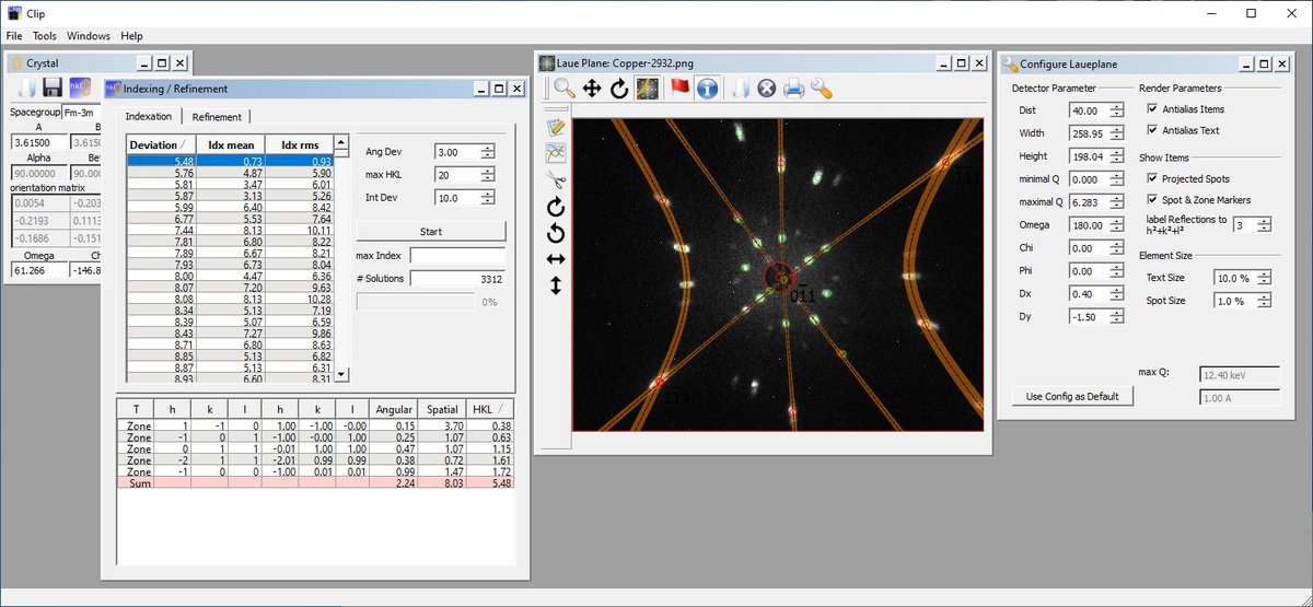
CLIP will return a number of index options.
They may be sorted via their Deviation and/or their ldx rms, with smaller values being better matches.
Click on one of the options to see it displayed, and use the arrow keys to scroll through the options.
Look carefully at the match between the projected and measured spots to decide which is the best indexing option.
Don't forget to have the Projected Spots option toggled 'on' in the Configure Laueplane window!
CLIP tools
CLIP has a number of diagnostic tools that help to assess the correct orientation for your crystal.
It uses an orthogonal (xyz) coordinate system defined as:
- the Vertical (z) axis, which is always the axis for the omega motor on OrientExpress.
- the Primary Beam (x) axis points along the direct beam, toward the reactor. This corresponds to the tilt2 motor when omega = 0.
- the Horizontal (y) axis points towards the Chartreuse mountain range (away from the IN16 guide). This corresponds to the tilt1 motor when omega = 0.
Note that the CLIP and OrientExpress coordinate systems only coincide when omega = 0. If omega is not zero, the CLIP xy and OrientExpress tilt1/tilt2 axes are no longer collinear.
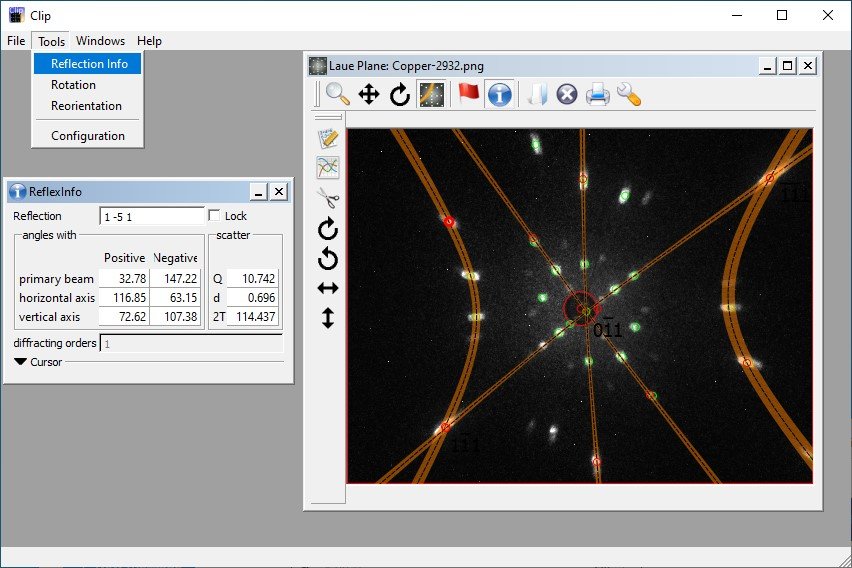
Once the data have been successfully indexed, the Tools: Reflection Info menu option will open the ReflexInfo window.
Making the Laue Plane window active and hovering over the Projected Peak positions will give information on the Miller indices, the momentum transfer and d-spacing, and the angles that the peak makes with respect to the important instrument axes.
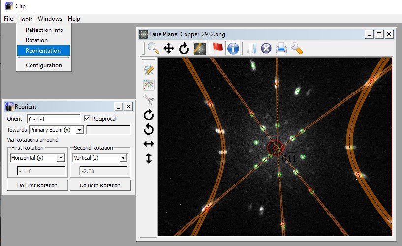
Once the data have been successfully indexed, the Tools: Reorientation menu option will open the Reorient window.
This is very useful for determining how close the alignment is to perfect.
- Enter the desired vector in the Orient field.
- Use the checkbox immediately to the right to specify whether the vector is real space or reciprocal space.
- Choose the desired direction for the vector relative to the instrument in the Towards field.
- Choose the rotation axes directions and the order for the rotations in the Via rotations fields
The rotation angles will appear below.
Having the First rotation around the Horizontal (y) axis is particularly useful (c.f. figure below), as this angle will show how far a desired scattering plane is from horizontal.
To have confidence that the indexing is correct, the crystal can be rotated by a set angle and another image can be measured.
CLIP can then be used to predict the position of the spots. Once the new spot positions are calculated, the new image can be loaded. If the indexing is correct, the predicted and measured spot positions will coincide.
The predicted spot positions for the rotated sample can be calculated using the Rotation tool.
The Tools: Rotation menu option will open the Rotation window.
The rotation axis is selected from the drop menu at the top of the Rotation window. Note the CLIP and OrientExpress coordinate systems written above.
The rotation can be changed by set increments of ±1° or ±5° using the buttons.
The rotation can be changed by an arbitrary value by typing a number in the Angle field.
As an example:
- Measure and index an image.
- Rotate omega by +30° and collect another image.
- Use the Rotation tool in CLIP to rotate the Vertical (z) axis by +30°.
- Open the new image in CLIP. If the indexing is correct, the predicted and measured spots will coincide.
Note that similar rotations can be performed by changing the values in the Omega, Chi, and Phi fields of the Crystal window, however these correspond to Euler cradle angles.
While the Omega angle corresponds to the omega motor on OrientExpress, Chi, and Phi do not correspond to the tilt1 and tilt2 motors. The Rotation tool is a more intuitive method for calculating rotations as it allows for rotation about orthogonal axes.
