print

IN5

Disk chopper time-of-flight spectrometer

News from IN5

IN5 animation

To see the inner workings of the time-of-flight instrument IN5, have a look at the film. 

IN5B instrument characteristics

N5 resolution in a nutshell

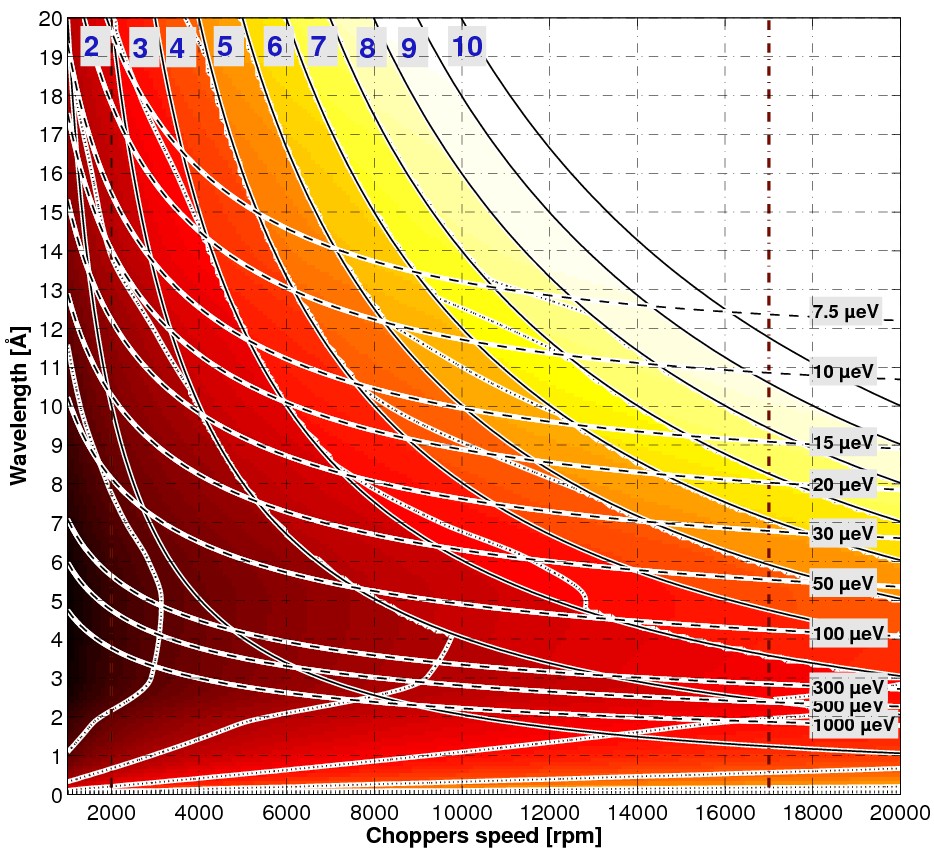
Double entry plot extracted from the analytical formulae [1]. The green lines are the IN5B resolutions vs the chopper velocity (X-axis) and the wavelength (Y-axis).
The white lines define regions with different frame overlap ratio (a region where N=3 means that we need to spin the frame overlap chopper 3 times slower - 2 neutron pulses over 3 lost - than the other choppers to avoid frame overlaping) according to the rule λmax = 1.5 λo where λo is the incident wavelength. The numbers stands for the frame overlap ratio.

As an example, a wavelength of 5 Å and a chopper velocity of 8500rpm give a resolution of 100 µeV with a frame overlap ratio of 3 (as we are close from the boundary a ratio of 2 might be also correct).

The color scale superimposes the measured absolute flux with the above calculated figure. It combines with the measured flux (see below).

Absolute flux measurements

The figure below shows the absolute flux as measured by gold foil activation for one velocity, 8500 rpm, i.e. half the maximal velocity, for a frame overlap ratio of 1 (same velocity for all the choppers). Doubling this velocity leads to a loss of flux by a factor 2.

Compute your own optimal resolution/flux parameters

The neutron intensity (here the neutron current I[n/cm2/s]) depends on the incident flux, the chopper velocities and the frame overlap ratio: 

ΦOλ [n/cm2/s] is the absolute flux per wavelength (unknown), N is the frame overlap ratio (see Fig. 1 above) and ω is the master chopper velocity.
With IOλ coming from Fig. 2 above, we have then: 

1. R.E. Lechner, Proceedings of the ICANS-XI, KEK reports 90-25 (Eds: M. Misawa, M. Furusaka, H. Ideka, N. Watanabe, 1991).

The routines contained in reduce are now part of the data reading of Lamp:
unchecking the "raw" box on the main interface or setting RDSET,/noraw in a batch .prox file produces the S(2 theta, time-of-flight) 2D spectra of the read data. Cases where there is no elastic peak in the spectra are handled by reading first a reference  raw file ( with strong elastic peak) and then reading the data. The routines included in "reduce.prox" below are thus no more needed.

The reduced S(2θ, ToF) data are also stored in hdf format (hierarchical data format) a file which name is:
run_<first number>_<last number>_ToF.hdf.
For further data treatment concerning the standard S(2θ, ToF) it is only necessary to load (transparently in LAMP) the saved processed data.

Bugs reports and questions to: J. ollivier (ollivier(at)ill.fr)

The standard instrumental corrections (background substraction, vanadium normalisation, ...) are made starting from the saved .hdf files coming out from the above steps. It is theoretically possible to reuse the INX program but there lack a routine transforming the hdf data into the former time-of-flight ASCII raw data format. In order to use your own set of routines the easiest is to import the hdf data in your routines thanks to the numerous library able to import / export the well known hdf format.

All the operations made previously within INX (or equivalent software) can be made within LAMP. A "prox" template is accessible from LAMP: standard1.prox through the "Users batch file, MACROS" menu. The different steps of a standard data reduction are explained in the file. All the steps are not compulsory depending on the type of data reduction expected (S(2θ,ω) or S(Q,ω),... ). Comment or remove the unwanted lines of the prox in your working directory.

While using the LAMP runtime version, before playing the standard1.prox batch file below, you will need to have access to the specific (compiled) IN5 routines. The routines are in a Lamp plugging available in the Lamp runtime distribution or can be download through the "Liveupdate" within Lamp.

Click on standard1.prox to have a look at the standard procedure. 

Output data format might be chosen between the conservative INX (CROSSX) format for those who have their fitting routines reading this format or the HDF format that keep the parameters set of the experiment in each file. This format might be also lighter in disk space.

For a single crystal experiment all the pixels of the detectors are processed individually or after grouping. There is also less transformation steps, althugh more data to process. A file named singleCrystal.prox is in the same directory than above and can be stored on the working directory if changes are needed though the LAMP menu.

singleCrystal.prox

Data are stored in the SPE text format to be read and analysed with "mSlice" or the Horace suite from ISIS. They can be stored in HDF format as well by changing the storage routine. The miscellaneous files PHX and PAR files are also created while storing the data. They can then be directly processed using the above mentioned routines provided you find a Windows 32bits with Matlab intalled with 4Gb of RAM.

Single crystal utilities

Some tools concerning the single crystal data treatment from IN5 data:

  1. How to create the .spe files with Lamp
  2. Generate the (Horace) .sqw file from the .spe fiels
  3. Extracting cuts in the reciprocal space with Horace

Create .SPE files - singlecrystal.prox

; --------------------------------------------------------------------------------
;
;  @singlecrystal
;
;  
; Data reduction for single crystals.
; Output the data in .spe format for use with , e.g., mSlice
; or Homer suite.
;
; Essentially no corrections on the data ( no empty substraction
; and no energy detector efficiency corrections - rather of low interest
; for low temperature inelastic scattering on the Stokes side)
;
;
;
;  Reduction of the data size (745Mb) since run an out of memory
;  with this data size- to ~ 200Mb only.
;
;
;
;  Last revised: JOR (ollivier@ill.eu) Mon Aug 31 14:42:58 CEST 2009
; --------------------------------------------------------------------------------
rdset, base="Current Cycle"
; --------------------------------------------------------------------------------
;  b and e must be defined as the first and last run to add
;  in the spectrum.
;  Can be defined here or anywhere else under lamp (global variable)
; --------------------------------------------------------------------------------
;    b = 64215
;    e = 64220
; --------------------------------------------------------------------------------
; 0) Define the graining ratio [f, g, h] = [E, Phi, Z]
; --------------------------------------------------------------------------------
f = 1
g = 2
h = 2
; --------------------------------------------------------------------------------
; 1)  Load the data:
;
;  1 run rdrun, 1.2) if more than one run: rdsum
;   Wed Dec 10 18:13:33 CET 2008: Normalise works fine now after rdsum
;   (data since Tuesday dec 09 2008)
; --------------------------------------------------------------------------------
print, "FULL3D: Load No ",strtrim(b,2)," to ",strtrim(e,2)," ..."
; --------------------------------------------------------------------------------
if e eq b then w1 = rdrun(b) else w1 = rdsum(b,e)
; --------------------------------------------------------------------------------
; 1) Correction for the distance (average = 4.0 m)
; --------------------------------------------------------------------------------
w1 = in5_distanceCorrection(w1, /verbose)
; --------------------------------------------------------------------------------
; 2) Monitor normalisation
; --------------------------------------------------------------------------------
w1 = in5_normalise(w1, /verbose)
; --------------------------------------------------------------------------------
; 3) Regularise scattering angles Phi
;   not requested for single Xtals
; --------------------------------------------------------------------------------
;  w2 = regularise(w1, /verbose)
; --------------------------------------------------------------------------------
; 4) Transforme in energy
;    in: [Phi,z,ToF]  ---> out: [E,Phi,z]
; --------------------------------------------------------------------------------
w3 = in5_t2epsd(w2, /verbose)
; --------------------------------------------------------------------------------
; 5) Reduce the energy scale to the useful one
; in order to have an integer divisor for the rebin, use this:
; (240 channels in Z instead of 241)
; --------------------------------------------------------------------------------
i  = where(x3 gt -1.0)
w4 = w3(i,*,1:*)  & e4 = e3(i,*,1:*)
x4 = x3(i)
z4 = z3(1:*)
; --------------------------------------------------------------------------------
; 4) Rebin the data
;    To use the rebin function , numbers of elements should be an interger
;    ratio.
;   WARNING: congrid doesn't average properly: statistics is not conserved but
;            rebin do.
; --------------------------------------------------------------------------------
s  = size(w4)
w5 = rebin(w4, s(1)/f,s(2)/g,s(3)/h)
e5 = rebin(e4, s(1)/f,s(2)/g,s(3)/h)
; x5 = rebin(x4,s(1)/f) ; unusefull
y5 = rebin(y4,s(2)/g)
z5 = rebin(z4,s(3)/h)
s  = size(w5)
; --------------------------------------------------------------------------------
; 5) Save the data and create the phx file accordingly
; --------------------------------------------------------------------------------
c = 'sqw_'+strtrim(string(b),2)+'_'+strtrim(string(e),2)+'_'+strtrim(string(s(1)),2)+'_'+strtrim(string(s(2)),2)+'_'+strtrim(string(s(3)),2)
in5_outputspe, w5, file=c, /phx, /verbose
; --------------------------------------------------------------------------------
;  Gzip the files to spare space (must be unzipped for use with mSlice)
; --------------------------------------------------------------------------------
; spawn,"gzip "+c+".spe"


create_sqw_template

Generating SQW file

Generate the data file in the reciprocal space of the crystal (.sqw) from the datasets in the instrument frame (.spe) using the Horace distribution in Matlab.
The .spe files being generated before using, e.g., Lamp (see create .SPE files).

Contents

% ----------------------------------------------------------%%   create_17K_2p0A%% ----------------------------------------------------------
horace_on()

clear, close all
!==================================================================!
!                      HORACE                                      !
!------------------------------------------------------------------!
!  Visualisation of multi-dimensional neutron spectroscopy data    !
!                                                                  !
!  T.G.Perring, J van Duijn, R.A.Ewings         November 2008      !
!------------------------------------------------------------------!
! Matlab  code: $Revision:: 558  $ ($Date:: 2011-07-19 11:06:05 $) !
! Mex code:    Disabled  or not supported on this platform         !
!------------------------------------------------------------------!

Define working directories

% ----------------------------------------------------------% Define working directories% ----------------------------------------------------------% Windows% dirroot  = '\\serdon-nv\illdata\133\in5\exp_4-01-1230\';% dirfinal = [dirroot,'processed\spe\'];% dirraw  =  [dirroot,'rawdata\'];% linux
dirroot  = '/usr/illdata/133/in5/exp_4-01-1230/';
dirfinal = [dirroot,'processed/spe/'];
dirraw  =  [dirroot,'rawdata/'];

indir      = dirfinal;                             % directory of spe files
par_file   = [dirfinal,'in5psd_318_384_240.par'];  % detector parameter file
sqw_file   = [dirfinal,'tmo_2p0A_17K.sqw'];        % output sqw file

Initial parameters

Lambda = 2.0;                          % Wavelenght [A]
efix   = 81.805/Lambda^2 ;             % Ei [meV]
emode  = 1;                            % Direct geometry (2: inverse)
alatt  = [5.297, 5.831, 7.403];        % Crystal parameters (from literature)
angdeg = [90.0,90.0,90.0];
u      = [0,1,0];                      % 1st reference axis: u=// to incident beam
v      = [0,0,1];                      % 2nd reference axis: v=perp to incident beam
omega=0;dpsi=0;                        % Unuseful (?)
gl=2.37;   % Estimated from the Braggs at level
gs=1.003;  %   --"--% Or left to zero and orientation corrected on .SQW files later% (see horace_rotation_corrections).

Sample rotation offset

Omega = Omega_0 when Ki is parallel to the first reference axis (u)

% ----------------------------------------------------------% Sample rotation offset (determined from Braggs positions)% ----------------------------------------------------------
Offset = 250.32 - 180.0;

Proceed

Give all sample rotation angles (as measured) and corresponding .spe files (generated in Lamp at present). Sort them (not compulsory), check Omega with the angle recorded in the raw datafiles and proceed to the projection in crystal reciprocal space (generate .sqw file).

% Sample rotation angles as given from the measurements
Omega  = [240:-2:234,232:-2:120,121:2:139,141:2:233]';
% Run numbers corresponding to the sample rotation
irun   = [110017:110020,110023:110079,110080:110089,110091:110137]';
[Omega, ind] = sort(Omega);

% Sample rotation without offset
psi = Offset - Omega;

irun = irun(ind);
nfiles = numel(irun);
spe_file = cell(1,nfiles);

% Cell matrix of spe files to usefor k=1:nfiles
    spe_file{k}=[indir,'sqw_',num2str(irun(k,1)),'_',num2str(irun(k,1)),'_318_384_240.spe'];
end% Check consistency (compare the sample rotation angle with the value in each file)for k = 1:nfiles
    rawFile = [dirraw,num2str(irun(k,1)),'.nxs'];
    SROT=0;
    SRot = hdf5read(rawFile, '/entry0/instrument/SRot/value');
    fprintf('%d)\tPsi = %5.2f ( Om = %5.2f / SRot = %5.2f) -> %s \n',k, psi(k),Omega(k),SRot,spe_file{k});
end
1)  Psi = -49.68 ( Om = 120.00 / SRot = 120.01) -> /usr/illdata/133/in5/exp_4-01-1230/processed/spe/sqw_110079_110079_318_384_240.spe 
2)  Psi = -50.68 ( Om = 121.00 / SRot = 120.99) -> /usr/illdata/133/in5/exp_4-01-1230/processed/spe/sqw_110080_110080_318_384_240.spe 
3)  Psi = -51.68 ( Om = 122.00 / SRot = 122.01) -> /usr/illdata/133/in5/exp_4-01-1230/processed/spe/sqw_110078_110078_318_384_240.spe 
4)  Psi = -52.68 ( Om = 123.00 / SRot = 122.99) -> /usr/illdata/133/in5/exp_4-01-1230/processed/spe/sqw_110081_110081_318_384_240.spe 

...
116) Psi = -165.68 ( Om = 236.00 / SRot = 236.01) -> /usr/illdata/133/in5/exp_4-01-1230/processed/spe/sqw_110019_110019_318_384_240.spe 117) Psi = -167.68 ( Om = 238.00 / SRot = 238.01) -> /usr/illdata/133/in5/exp_4-01-1230/processed/spe/sqw_110018_110018_318_384_240.spe 118) Psi = -169.68 ( Om = 240.00 / SRot = 239.99) -> /usr/illdata/133/in5/exp_4-01-1230/processed/spe/sqw_110017_110017_318_384_240.spe
% Generate the .SQW file
gen_sqw (spe_file, par_file, sqw_file, efix, emode, alatt, angdeg, u, v, ...
         psi , omega, dpsi, gl, gs);
correction_sample_misalignment

Contents

% CORRECTION_SAMPLE_MISALIGNMENT Correcting for sample misalignments in Horace%% Corrections of the sample mis-alignments and lattice parameter% refinement. (from the script on the Horace website )% To be done after the creation of the .sqw file%% 1) Check which Bragg peak to deal with (in 3 directions)% 2) Once the notional Braggs are defined, refine the Braggs% 3) Compute the corrections% 4) Apply corrections to the .sqw file%
clear, close all

Parameters to enter

sqw_file   = 'spe/Alcur_155K.sqw';  % .sqw file to correct% projection axes
proj.u = [1,1,0];
proj.v = [0,0,1];
proj.type = 'rrr';
proj.uoffset = [0,0,0,0];
% Lattice parameters
alatt  = [8.22,8.22, 11.02];
angdeg = [90,90,120];

Look for Braggs

%Make a series slices in order to work out what Bragg positions we have.
dQ = 0.025;
H = 0; dH = dQ;
K = 0; dK = dQ;
L = 0; dL = dQ;
E = 0; dE = 0.125;
alignment_slice1=cut_sqw(sqw_file,proj, dH, dK,[L-dL, L+dL],[E-dE, E+dE],'-nopix');
alignment_slice2=cut_sqw(sqw_file,proj, [H-dH, H+dH], dK,dL,[E-dE, E+dE],'-nopix');
alignment_slice3=cut_sqw(sqw_file,proj, dH, [K-dK, K+dK],dL,[E-dE, E+dE],'-nopix');


plot(compact(alignment_slice1)); keep_figure; lc 01
plot(compact(alignment_slice2)); keep_figure; lc 01
plot(compact(alignment_slice3)); keep_figure; lc 01

Define notional Bragg peaks

Notional Bragg peaks = rlu

bp=[1,1,0; 2,2,0; 0,0,6; 1,1,2; 1,1,-2];

Refine the Bragg peak positions


%Get true Bragg peak positions

% longitudinal extend, bin width, thickness
% transversal  extend, bin width, thickness
% dE
% 
% longitudinal cuts: 
%  wl = cut_sqw(sqw_file, proj, [-longit. extend/2, longit. bin, lomngit. extend/2], ...
%                               [-transverse thick, transverse bin, +transverse thick],  ...
%                               [-transverse thick, transverse bin, +transverse thick], [-dE, +dE], '-nopix'); 
%
% transverse cuts:
%  wt1= cut_sqw(sqw_file, proj, [-longit. thick/2,+longit. thick/2], ...
%                               [-trans. extend/2, trans. bin,+trans. extend/2] , ...
%                               [-trans. thick/2,+trans. thick/2], [-dE, +dE], '-nopix');
%
%  wt2= cut_sqw(sqw_file, proj, [-longit. thick/2,+longit. thick/2], ...
%                               [-trans. thick/2,+trans. thick/2], [-dE, +dE], ...
%                               [-trans. extend/2, trans. bin,+trans. extend/2], '-nopix');
%
%

[rlu0,~,wcut,wpeak]=bragg_positions(sqw_file, bp, ...
                                        0.5, 0.0125, 0.25,...
                                        0.5, 0.0125, 0.25, 0.1, 'gauss','bin_ab');

%Check how well the function did:
bragg_positions_view(wcut,wpeak)
--------------------------------------------------------------------------------
Peak 1:  [1  1  0]    scan: 1 (radial scan)
--------------------------------------------------------------------------------
Peak 1:  [1  1  0]    scan: 2 (transverse scan)
--------------------------------------------------------------------------------
Peak 1:  [1  1  0]    scan: 3 (transverse scan)
--------------------------------------------------------------------------------
--------------------------------------------------------------------------------
Peak 2:  [2  2  0]    scan: 1 (radial scan)
--------------------------------------------------------------------------------
Peak 2:  [2  2  0]    scan: 2 (transverse scan)
-------------------------------------------------------------------------------- 
Peak 2:  [2  2  0]    scan: 3 (transverse scan)
--------------------------------------------------------------------------------
--------------------------------------------------------------------------------
Peak 3:  [0  0  6]    scan: 1 (radial scan)
--------------------------------------------------------------------------------
Peak 3:  [0  0  6]    scan: 2 (transverse scan)
--------------------------------------------------------------------------------
Peak 3:  [0  0  6]    scan: 3 (transverse scan)
--------------------------------------------------------------------------------
--------------------------------------------------------------------------------
Peak 4:  [1  1  2]    scan: 1 (radial scan)
--------------------------------------------------------------------------------
Peak 4:  [1  1  2]    scan: 2 (transverse scan)
--------------------------------------------------------------------------------
Peak 4:  [1  1  2]    scan: 3 (transverse scan)
--------------------------------------------------------------------------------
--------------------------------------------------------------------------------
Peak 5:  [1  1 -2]    scan: 1 (radial scan)
--------------------------------------------------------------------------------
Peak 5:  [1  1 -2]    scan: 2 (transverse scan)
--------------------------------------------------------------------------------
Peak 5:  [1  1 -2]    scan: 3 (transverse scan)
--------------------------------------------------------------------------------

Compute the corrections

%Determine corrections to lattice and orientation:
[rlu_corr,alatt,angdeg] = refine_crystal(rlu0, alatt, angdeg, bp,'fix_angdeg','fix_alatt_ratio');

Apply changes to sqw file

choice = questdlg('Apply changes to sqw file?', 'Confirm dialog', 'Ok', 'Cancel','Cancel');
if strcmp(choice,'Ok')
    change_crystal_horace(sqw_file, rlu_corr);
end
cuts_template

Cuts in the crystal reciprocal space

Cuts in 3, 2 or 1 dimension in any directions in the reciprocal space ofthe crystal using still Horace.

Contents

% ---------------------------------------------------------------------%  cuts% ---------------------------------------------------------------------
clear, close all% Windows% dirroot  = '\\serdon-nv\illdata\133\in5\exp_4-01-1230\';% dirfinal = [dirroot,'processed\spe\'];% linux
dirroot  = '/usr/illdata/133/in5/exp_4-01-1230/';
dirfinal = [dirroot,'processed/spe/'];

% Name of the .sqw file
data_source  = [dirfinal,'tmo_2p0A_17K.sqw'];    % output sqw file

Projection axes

Define a projection axes for the cut. Could be any orientation in the spanned reciprocal space, in particular, different from the one used to generate the .sqw file.

proj.u = [0,1,0];         % 2 perpendicular axes, the 3rd is calculated
proj.v = [0,0,1];
proj.type = 'rrr';        % units: 'r' means r.l.u, 'a' mean A-1
proj.uoffset = [0,0,0,0]; % Origin offset of the cut

3D cut in the [u,v,w] plane at fixed energy

With u=[010] and v = [001] this is volume [HKL,hw=0]

%                              u    v    w       hw
w1 = cut_sqw(data_source,proj,0.05,0.05,0.05,[-0.1,0.1]);
plot(w1)    % 3D plots with sliceomatic
view(0,0)

% Optionally smooth  before plotting
w2=d3d(w1);
w3=smooth(w2,[2,2,2]);
plot(w3);
view(0,90)

lc 01e-5% Color axis in 3D plots

3D cut in the [u,v,hw]: equatorial plane

With u=[010] and v = [001] this is volume [0KL,hw]

%                              u    v         w      hw
w1 = cut_sqw(data_source,proj,0.05,0.05,[-0.05,0.05],0);
plot(w1)    % 3D plots with sliceomatic
view(0,0)

% Optionally smooth  before plotting
w2=d3d(w1);
w3=smooth(w2,[2,2,2]);
plot(w3);
view(0,90)

3D cut in the [u,w,hw]: a vertical plane

With u=[010] and v = [001] this is volume [H0L,hw]

%                              u         v       w   hw
w1 = cut_sqw(data_source,proj,0.05,[-0.05,0.05],0.05,0);
plot(w1)    % 3D plots with sliceomatic
view(0,0)

% Optionally smooth  before plotting
w2=d3d(w1);
w3=smooth(w2,[2,2,2]);
plot(w3);
view(0,90)

2D cut in the [u,0,hw] direction

With u=[010] and v = [001] this is plane [0K0]

%                              u         v            w      hw
w1 = cut_sqw(data_source,proj,0.05,[-0.05,0.05],[-0.05,0.05],0);
plot(w1)   

% Optionally smooth  before plotting
w2=d2d(w1);
w3=smooth(w2,[2,2]);
plot(w3);

lz 01e-5% Color axis in 2D plots

2D cut in the [u,v,fixed hw]: iso-energy planes

With u=[010] and v = [001] this is plane [0KL] at hw = 1meV

%                             u     v         w          hw
w1 = cut_sqw(data_source,proj,0.05,0.05,[-0.05,0.05],[0.95,1.05]);
plot(w1)    

% Optionally smooth  before plotting
w2=d2d(w1);
w3=smooth(w2,[2,2]);
plot(w3);

1D cut in the [fixed u,fixed v, hw]: iso-energy planes

With u=[010] and v = [001] this is at position [001] u v w hw

w1 = cut_sqw(data_source,proj,[-0.05,0.05],[0.95,1.05],[-0.05,0.05],0);
plot(w1)    


Save the plot

Plot type can be 'pdf', 'jpeg', 'png', 'tif', 'eps',...

printplot2('figure.pdf',gcf,'pdf');

The compiled IN5 specific routines are accessible as a plugin to Lamp which is managed by the Lamp plugging management tool:

In Lamp , do a "liveupate" and after a restart, while selecting the IN5 instrument the corresponding plugging should be loaded.

If using LAMP with an IDL licence one can alternatively compile the routines found in sources_in5.tar.gz (gz - 89 Ki).

Bugs reports and questions to: J. ollivier (ollivier(at)ill.fr)

; ---------------------------------------------------------------------

;
;  @standard1
;
;
;
;   Template for standard nuclear scattering data reduction
;   To be used after the basic data reduction as made with "@reduce"
;
;
;  Last revised: JOR (ollivier@ill.eu), Mon Aug 31 16:37:07 CEST 2009
; ---------------------------------------------------------------------
RDSET,inst="IN5"            
RDSET,base="Current Path"            
; ---------------------------------------------------------------------
s  = '1-38,390-395'     ; bad spectra numbersto remove...
n  =  15                ; n grouping spectra
t  =  0.95              ; Sample transmission
v  =  0.890             ; vanadium transmission
c  = "sample.dat"       ; Name of the output file
; ---------------------------------------------------------------------
;
;   1)             Sample
;
; ---------------------------------------------------------------------
; 1.1.1) load sample (already normalized to monitor or time X 1000)
; ---------------------------------------------------------------------
w1 = rdrun('sample_ToF.hdf')

; ---------------------------------------------------------------------
; 1.1.2) Eventually remove spectra
; ---------------------------------------------------------------------
w1 = in5_remove_spectra(w1,badSpectra=s, /verbose)

; ---------------------------------------------------------------------
; 1.2.1) Empty Cell sample (or buffer)
;        Substraction should be done on raw data
; ---------------------------------------------------------------------
w2 = rdrun('emptycell_ToF.hdf')

; ---------------------------------------------------------------------
; 1.2.2) Eventually remove bad spectra
; ---------------------------------------------------------------------
w2 = in5_remove_spectra(w2,BadSpectra=s, /verbose)

; ---------------------------------------------------------------------
;  1.3) Do sample - t*EC        
; ---------------------------------------------------------------------
w3 = w1 - t*w2
e3 = sqrt(e1^2+(t*e2)^2)

; ---------------------------------------------------------------------
;  1.4) Correct for self-shielding/self-absorption
;  (VF. Sears like) for sample
;
; thick   = thickness [mm]
; rin      = cylinder inner radius [mm]
; rout     = cylinder outer radius [mm]
; angle   = slab angle [deg]
; sigma_a = absorption cross section [barns]
; sigma_s = total scattering cross section [barns]
; rho     = density [g/cm^3]
; Mass    = atomic mass [g]
;
; For a slab:
; ---------------------------------------------------------------------
w3 = in5_safcorr(w3,thick=0.3,angle=135.0,sigma_a=2.3234,sigma_s=95.09,rho=1.49,Mass=29.05, /verbose)

; For a hollow cylinder:
; ---------------------------------------------------------------------
;  w3 = in5_safcorr(w3,rin=114.0, rout=15.0,sigma_a=2.3234,sigma_s=95.09,rho=1.49,Mass=29.05, /verbose)

; For a full cylinder:
; ---------------------------------------------------------------------
;  w3 = in5_safcorr(w3, rin=8.0,sigma_a=2.3234,sigma_s=95.09,rho=1.49,Mass=29.05, /verbose)
 
 
; ---------------------------------------------------------------------
;
;  2)          Vanadium
;
; ---------------------------------------------------------------------
; 2.1) load vana
; ---------------------------------------------------------------------
w4 = rdrun('vanadium_ToF.hdf')

; ---------------------------------------------------------------------
; 2.2) Eventually remove bad spectra
; ---------------------------------------------------------------------
w4 = in5_remove_spectra(w4,badSpectra=s, /verbose)

; ---------------------------------------------------------------------
; 2.3) Empty Cell: use Same as above
; ---------------------------------------------------------------------
; ---------------------------------------------------------------------
; 2.5) Do vanadium - EC        
; ---------------------------------------------------------------------
w6 = w4 - v*w2 & e6 = sqrt( e4^2 + (v*e2)^2 )
; ---------------------------------------------------------------------
;  2.6) Correct for self-shielding/self-absorption
;  (VF. Sears like) for vanadium
;
; thick   = thickness
; angle   = slab angle
; rin      = cylinder inner radius [mm]
; rout     = cylinder outer radius [mm]
; sigma_a = absorption cross section
; sigma_s = total scattering cross section
; rho     = density
; Mass    = atomic mass
;
; ---------------------------------------------------------------------
w6 = in5_safcorr(w6,thick=1.0,angle=135.0,sigma_a=5.98,sigma_s=5.205,rho=5.96,Mass=50.941,/verbose)

; For a hollow cylinder:
; ---------------------------------------------------------------------
;  w6 = in5_safcorr(w6,rin=114.0, rout=15.0, sigma_a=5.98, sigma_s=5.205, rho=5.96, Mass=50.941,/verbose)
 
; For a full cylinder:
; ---------------------------------------------------------------------
;  w6 = in5_safcorr(w6, rin=8.0, sigma_a=5.98,sigma_s=5.205,rho=5.96,Mass=50.941,/verbose)


; ---------------------------------------------------------------------
;
; 3)  Normalize by the elastic peak of the vanadium          
;
;  
;   (vnorm correct the vana from DWF first.)
;
;
; ---------------------------------------------------------------------
w7 = in5_vnorm(w3,w6,/verbose)

; ---------------------------------------------------------------------
;
; 4) Correction for detector wavelength-efficiency +
;    remove flat bkgd.
;   /psd means take the same correction for all IN5 angles
;        that was not the case for the former IN5 with the 3 different type of
;        detectors - reduced to 2 in SAF corrections.
;   Other solution : mimic IN6 with rdset, inst="in6"
;                    Warning: for corrtof only.
;
; ---------------------------------------------------------------------
w7 = in5_corrtof(w7, /deteff, /psd, /background , /verbose)

; ---------------------------------------------------------------------
;
; 5) Conversion to S(2*theta, omega)
;
; ---------------------------------------------------------------------
w8 = in5_t2e(w7,/verbose)

; ---------------------------------------------------------------------
;
; 6) Group spectra in n groups
;
; ---------------------------------------------------------------------
  w9 = in5_group(w8,n,/verbose)

; ---------------------------------------------------------------------
;
; 7) Force constant energy bins for convolution in the fit
;
;    dE = 0.02, energy min in  up-scattering (AS) = -10.0
;    
;
; ---------------------------------------------------------------------
w10 = in5_energy_rebin(w9,de=0.02,Emin=-10.0,/force)

; ---------------------------------------------------------------------
;
; 8) Write data S(2*theta,w) format INX
;
; ---------------------------------------------------------------------
write_lamp,c+, w = 10,format = "inx"

; ---------------------------------------------------------------------
;
; 8) Write data S(2*theta,w) format hdf ...
;
; ---------------------------------------------------------------------
;  write_lamp,c, w = 10,format = "hdf"
;  spawn,"mv "+c+"_LAMP.hdf "+c+".hdf"

; ---------------------------------------------------------------------
;  Further treatments
; ---------------------------------------------------------------------
;
; 9) Constant Qelas rebinning
;    Q step = 0.02, energy min in  up-scattering (AS) = -10.0
;  
; ---------------------------------------------------------------------
; w12 = in5_sqw_rebin(w10, dq=0.02, Emin=-10.0, /verbose)
;
;
;
; ---------------------------------------------------------------------
; WARNING:
;
;  Transpose matrix after sqw_rebin before storing in the INX format
;  
; ---------------------------------------------------------------------

help on in5_ IDL routines

Last modified: Thu Oct 15 15:52:34 2009.

List of Routines

NAME:

corrtof, w_in, deteff = deteff, background = background, psd = psd, frameoverlap = frameoverlap

For IN4, IN5, IN6 and D7 data.

KEYWORDS:

/deteff : corrects for energy-variation of detector efficiency

/frameoverlap : subtracts a t^-4 tail from the beginning

of the time frame & shift the elastic peak

/background : subtracts a flat background in each detector,

found using a moving filter (For IN4, IN5 and IN6 only)

NO MORE VALID on the transformed data. Must be applied before

on the raw time-of-flight data.

The moving window width can be changed with the keyword:

window = [value] : default is 20. Must be used in conjunction with

/background

/psd : If inst = IN5 need this keyword for the detctor efficiency of the PSDs.

/verbose : More info during execution.

DIMENSIONS:

w_in=w_out(nchannels,nphases*nspectra)

COMMAND SYNTAX:

w2 = corrtof(w1[,/deteff][,/frameoverlap])

w2 = corrtof( w1,/deteff, window=15,/background, /verbose ) Since 10/2008 :

w2 = corrtof( w1,/deteff, /psd, window=15,/background, /verbose )

Keyword PSD means using the new PSD detectors.

(optional keywords shown in square brackets)

HISTORY:

written by: KHA,JRS 23/6/03

revisions: JO, 20/12/04 detector efficiency correction as implemented in

INX for IN4, IN5, IN6 and MIBEMOL.

JO, Mon Nov 24 14:17:47 CET 2008: Add detector efficiency as for 1 inch tubes

IN5/IN6 (wait for Van Esch calculation ?)

JO, Fri Jan 23 10:35:44 CET 2009: Correct the w_in background substraction: W_in

was affected by the substraction, not normal...

(See in5_corrtof.pro)

NAME:

energy_rebin For IN4, IN5, IN6 and D7 data.

rebins output workspace from t2e to constant energy bin width.

ARGUMENTS:

dE : required energy bin width

KEYWORDS:

/force : rebin over entire energy range

otherwise: rebin only where dE is > point spacing (default)

/keepelastic : do not rebin over the elastic peak

Emin = energy minimal to start the exit workspace.

DIMENSIONS:

w_in=(nE,nspectra) -> w_out(dE, nspectra)

COMMAND SYNTAX:

w10 = energy_rebin(w9,dE=<dE>[Emin=-100.0, /force, /keepelastic])

(optional keywords shown in square brackets)

VERSION HISTORY:

KHA,JRS 16/03/05 Modifications: JO, ??? add verbosity

JO, Tue Nov 25 11:12:49 CET 2008: Improve output parameters

presentation

(See in5_energy_rebin.pro)

For IN4, IN5, IN6 and D7 Rebins output data from t2e and reb to

regular-grid S(Q,w) data using the old KHA IN6 rebin algorithm.

Selects a single E-value. Input workspace must be in energy transfer

versus scattering angle, i.e. only one component or spin phase.

ARGUMENTS:

Evalue: E-value at centre of extracted strip

dE : Width of E-strip

dQ : Q bin width

KEYWORDS:

(- only for D7 data:)

/neg_angles : use only negative angles

/pos_angles : use only positive angles

/all_angles : use all angles (default)

input workspace must be in energy transfer versus scattering

angle, i.e. only one component or spin phase.

(ev, eb, qb and ib are obsolete, kept for backwards compatability)

DIMENSIONS:

w_in(nE,nphi) -> w_out(nE,nQ)

COMMAND SYNTAX:

w10 = estrip(w9,E = <Evalue>,dE = <dE>,dQ = <dQ>[,/pos_angles][,/neg_angles][,/all_angles],[/verbose])

(Optional keywords shown in square brackets)

HISTORY:

Creation : KHA,JRS 9/02/06

Modifications : JOR 2009/08 Reverse array direction for negative angles for D7 only!

Add prefix in5_ (= trusted IN5) and on demand verbosity.

(See in5_estrip.pro)

NAME:

group

PURPOSES:

Group spectra in scattering angle or Q in a smaller number of groups.

Intensity is the averaged value.

COMMAND SYNTAX:

w2 = group(w1,10, /verbose) ; group spectra in 10 groups with

output information

w2 = group(w1,filename='angles.ang', /verbose) ; group spectra according

to the file 'angles.ang'

ARGUMENTS:

number of groups : final group number

filename : name of a file where the spectra numbers are given

for each group.

Angles must be in column and in LAMP format, i.e., starting from 1

and going to 88, 90 before 2006 and up to 395 for the renewed IN5.

e.g.: 1 7

8 15

...

Means: group 1 include spectra 1 to 7, group 2, spectra 8 to 15, etc.

Last value lower than the number of remaining groups

after remove_spectra

Bad groups must have been removed

with remove_spectra first

/verbose : more info during execution

VERSION HISTORY:

Written by . S. Rols 11/01

Revisions:

+ S. Rols 10.08.02 rols@gdpc.univ-montp2.fr

+ M.Plazanet 2005: add the possibility to group according to

an angle group file 'angles.ang'

+ JO 2006-11-22: Improved version for the group file, verbosity added.

(See in5_group.pro)

NAME:

FUNCTION normalise, w_in, raw=raw, monitor=monitor, time=time, $

detector=detector, alldetectors=alldetectors,

ei=ei, $

madangles=madangles, zeroshift=zeroshift, nopo = nopo, $

inorm, ikeep

For IN4, IN5, IN6, HET and D7 data.

For IN4, IN5 and IN6:

---------------------

Normalises raw data to monitor or counting time, depending on value of

inorm. Finds the position of the elastic peak.

KEYWORDS:

/raw : no normlisation (error bars calculated)

/monitor : normalise data to 1000 monitor1 counts (DEFAULT)

/time : normalise data to counting time (will not work for summed data)

(inorm and ikeep are obsolete, kept for backwards compatability)

For HET:

--------

Normalises raw data to monitor 1 (must be monitor 1 for ISIS data).

Removes empty spectra. User must input incident energy.

ARGUMENTS:

ei : incident energy of measurement

For D7:

--------

Normalises raw data to monitor (default) or counting time or individual

detector. Extracts every other spectrum if desired (=> nbSpectra=32).

Recalculates detector angles based on a YIG calibration by default.

ARGUMENTS:

detector : detector number to normalise to

zeroshift : angle in degrees of 2theta = 0

(inorm and ikeep are obsolete, kept for backwards compatability)

KEYWORDS:

/raw : no normlisation (error bars calculated)

/monitor : normalise data to 1000 monitor1 counts (DEFAULT)

/time : normalise data to counting time

/alldetectors : supresses the removal of the odd numbered detectors

/madangles : supresses the recalculation of the detector angles using the

current YIG calibration

DIMENSIONS: non-TOF data: w_out(nbSpectra,nphases,nruns)

-unless nphases is 1

TOF data: w_out(nbChannels,nbSpectra*nphases,nruns)

DCOMMAND SYNTAX:

w2=normalise(w1[,/raw][,/monitor][,/time][,detector=#][,/alldetectors][,/rawangles][,ei=#])

(optional keywords/arguments shown in square brackets)

VERSION HISTORY:

Writtne by: KHA,JRS 29/7/04

Modifications: S. Rols 09/01 srols@anl.gov: Normalization for mibemol data and DCS

JO, ??? Add verbosity and use str_fit instead of fitgauss (due to)

problems with the errors computation.

JO, Tue Dec 9 18:12:50 CET 2008: correct normalise for the 3D raw data

with the new PSDs. Add ELP calculation

in that case.

(See in5_normalise.pro)

IN5_QSTRIP

For IN4, IN5, IN6 and D7 rebins output data from t2e and

reb to regular-grid S(Q,w) data using the old KHA IN6 rebin algorithm.

Selects a single Q-value. Input workspace must be in energy transfer

versus scattering angle, i.e. only one component or spin phase.

ARGUMENTS:

Qvalue: Q-value at centre of extracted strip

dQ : Width of Q-strip

KEYWORDS

(- only for D7 data)

/neg_angles : use only negative angles

/pos_angles : use only positive angles

/all_angles : use all angles (default)

input workspace must be in energy transfer versus scattering angle,

i.e. only one component or spin phase.

(ev, eb, qb and ib are obsolete, kept for backwards compatability)

DIMENSIONS:

w_in(nE,nphi) -> w_out(nE)

COMMAND SYNTAX:

w10 = qstrip(w9,Q=<Qvalue>,dQ=<dQ>[,/neg_angles][,/pos_angles][,/all_angles],[/verbose])

(optional keywords shown in square brackets)

HISTORY:

Creation : KHA,JRS 9/02/06

Modifications : JOR 2009/08 Reverse array direction for negative angles for D7 only!

Add prefix in5_ (= trusted IN5) and on demand verbosity.

(See in5_qstrip.pro)

NAME:

remove_spectra For IN4, IN5, IN6, DCS and HET, ...

Removes spectra with numbers given in array badspecs.

Spectrum numbers run from 1 to nspectra.

KEYWORDS:

/nolog : if set, supresses output of badspecs in other_tit

This is necessary in cases where other_tit exceeds 160 characters

/verbose : add verbosity to the standard output.

ARGUMENTS:

badspecs : array of spectrum numbers to be deleted

BadSpectra: String of bad spectra to remove.

Syntax is : '1-40,87,90,93,356-367'

'1-40' means all spectra from number 1 to number 40, etc.

DIMENSIONS:

w_in(nchannels,nspectra) -> w_out(nchannels,nspectra-n) - n=number of bad spectra

COMMAND SYNTAX:

w2 = remove_spectra(w1,[3,90,202]) (remember square brackets)

or (new version):

w2 = remove_spectra(w1,BadSpectra = '1-87,112-121,234,235,236,256-273',/verbose)

HISTORY:

KHA,JRS 7/05/05

JO, Mon Jun 16 14:24:35 CEST 2008 Modif to take a group of detectors instead

of individual numbers.

e.g. w2 = remove_spectra(w1,BadSpectra = '1-87,112-121,234,235,236,256-273')

in that case, the BadSpectra string replace the badspecs input.

(See in5_remove_spectra.pro)

NAME:

safcorr

PURPOSES:

Perform the Self Attenuation Factor corrections on data in w_in

similarly to INX routines.

For slab samples, the calculation is identical to INX as taken from the Sears

calculations (V.F. Sears Adv. Phys. (1975)).

For cylinders (full/hollow) the calculation is similar to those of J.Wuttke (ILL report WU....)

and differs slightly formt the calculation from Rieutord

(ILL report RI.... 1991) as implemented in INX but the results are similar.

In all cases, contrarily to the INx and SQW routines,

the SAF corrections are computed for each energy.

ARGUMENTS:

sigma_a: Absorption cross-section (barns)

sigma_s: Total scattering cross-section (barns)

rho: sample density (g/cm^3)

Mass: molar mass (g/mol)

Rin: Inner radius (full/hollow cylinders). Unit: [mm]

Rout: outer radius (full/hollow cylinders). Unit: [mm]

thick: Slab thickness (flat plate -- slab -- samples). Unit: [mm]

angle: Slab setting angle (flat plate -- slab -- samples). Unit: [deg.]

KEYWORDS:

/verbose: Information during the process

/corrections: Gives the Self Attenuation Factors instead of the corrected intensities

Size = size(w_in)

hlp = hlp Gives this help

DIMENSIONS:

Default: w_in=w_out(nchannels, nspectra)

If keyword '/corrections': gives the correction map Corr such as:

W_out = W_in/Corr instead of W_out.

COMMAND SYNTAX:

For a SLAB sample:

w8=safcorr(w7,thick=0.5,angle=135.0,sigma_a=5.08,sigma_s=5.205,rho=5.96,Mass=50.941)

Performs self-absorption / self-attenuation for w7

(here parameters are for vanadium slab at an angle of 135 deg)

(optional arguments shown in square brackets)

For a cylinder (full or hollow) sample:

w8=safcorr(w7,Rin=10.0,Rout=11.0,sigma_a=5.08,sigma_s=5.205,rho=5.96,Mass=50.941)

For a full cylinder set Rin=0 or cancel the keyword in the routine:

w8=safcorr(w7,Rout=11.0,sigma_a=5.08,sigma_s=5.205,rho=5.96,Mass=50.941)

w3 = safcorr(w2,Rin=0,Rout=12,sigma_a=5.08,sigma_s=5.205,rho=5.96,Mass=50.941,/verbose,/corrections)

for a vanadium full cylinder, gives the corrections factors instead of the corrected intensities

VERSION HISTORY:

Written by : J.Ollivier 2006-03-23

Modified by:

JO-2006-06-15: Corrected a bug 2 times win/H1 in safcyl

JO-2006-11-10: Compute energies. Data need no more to be in energy

mode. Warning: all cases are not treated , MIBEMOL

should not work.

JO-2008-11-25: Treat correctly the case where all is in time channel.

Improve verbosity.

(See in5_safcorr.pro)

NAME:

t2e

PURPOSES:

Converts array w_in to energy in w_out Based on the original "tee" procedure instead of on "t2e".

COMMAND SYNTAX:

w2 = t2e(w1)

convert tof spectrum in w1 to energy and output in w2

Energies are in x2.

w2 = t2e(w1,/verbose) ; same with information on the standard output.

w2 = t2e(w1,w3,/verbose) ; Uses an elastic peak standard raw data reference for finding the

elastic peak position (ELP).

The Vanadium or better the low temperature sample is this

reference usually. This is required each time the ELP is incorrectly

defined in the sample. E.g. on liquid spectra.

ARGUMENTS:

(all optional)

/average_elp : take average elp instead of

W_van : Workspace for the vanadium/low temp. sample, that gives the elastic peak reference

/verbose : more info during execution

DIMENSIONS:

w_in = w_out(nchannels, nspectra)

VERSION HISTORY:

Written by GJK 1994

Revisions: JO 2004-11-03 Include other Tof instruments (e.g.: MIBEMOL, LLB)

JO 2006-03-28 Html help, more verbosity

JO 2006-10-23 tee -> t2e with the same properties

in case the original t2e fails.

JO 2006-11-10 gaussian fit with str_fit instead of fitgauss (due to

problems when error bars are not computed), with the same restriction

to the elastic peak than before +/- 30 channels from

mean elastic maximum.

JO 2006-12-14 Reference of the elastic line by the vanadium (keyword: Wvan)

Vanadium data must be in the same format than sample data.

JO, 2007-11-05 Seems that the gauss ELP is 1 channel out from the reality.

Is it always true ???

JO, Sat Oct 11 11:57:30 CEST 2008: If spectra are zeros remove first and last index

str_fit gives the first X if no maxi found


JO, Thu Dec 4 10:55:17 CET 2008: correction on the index ind

(See in5_t2e.pro)

NAME:

t2epsd

PURPOSES:

Converts array w_in to energy in w_out fpr IN5 PSD in single Xtal mode

Same as in5_t2e but adapted for PSDs. ;

DIMENSIONS:

w_in = w_out(nchannels, nspectra, nZ)

VERSION HISTORY:

JO 2008-07-01 This version T2EPSD adapted for IN5 PSD but other instruments

removed for clarity.

(See in5_t2epsd.pro)

NAME:

vnorm

PURPOSES:

Normalises data in w_in with vanadium in (w_van0) elastic peak integral.

ARGUMENTS:

(all optional)

chmin : lower time channel limit of integration over vanadium elastic peak

chmax : upper time channel limit

/verbose : more info during execution

DIMENSIONS:

w_in=w_out(nchannels, nspectra)

COMMAND SYNTAX:

w3 = vnorm(w1,w2,chmin=<min>,chmax=<max>[,/verbose])

- normalises data in w1 to vanadium data in w2 and store the result in w3

(optional arguments shown in square brackets).

EXAMPLES:

w3 = vnorm(w1,w2,/verbose) ; calculation of the integration limit are automatic.

w3 = vnorm(w1,w2, chmin=490,chmax=520) ; only a few case require to put the limits

by hand.

VERSION HISTORY:

Written by : JR. Stewart,KH.Andersen 15/11/02

Modified by: S. Rols (for mibemol data) 4/12/03

J. ollivier (2006-03-21) New version with vanadium temperature correction for the Debye-waller factor.

Add verbosity on the standard output. Calculation of the integral limitsautomatic.

WARNING: D7 case removed for clarity of the code!!!

(See in5_vnorm.pro)