October 20, 2005
From Loudspeaker drives to Linear motors: A short story of velocity drives in BS spectroscopy
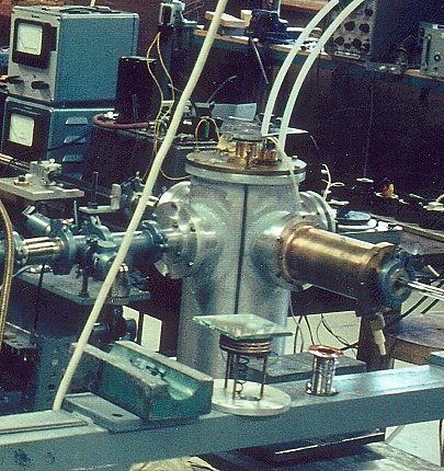
Alefeld was the first to use a velocity drive in neutron spectroscopy to vary the incident neutron wavelength. The photo below shows a modified loudspeaker drive attached to a N2 cryostat developed and used by Alefeld in 1968 to measure the lattice parameter change of SrTiO3 around the phase transition. This Doppler drive had originally been developed in the nearby Institute for Moessbauer spectroscopy. The maximum speed was only about 25 cm/s. The motion was driven electromagnetically with a sine wave generator ( frequency around 50 Hz) fed to loudspeaker coils recovered from HiFi woovers.
A copy of this drive ( see photo below) was later used on the first BS spectrometer at the FRMI. The micrometer device seen on the back of the drive was used to measure the maximum amplitude of the drive motion ( a few mm).
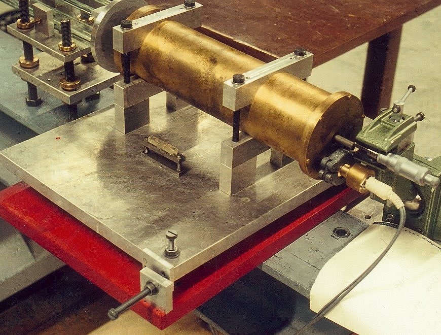
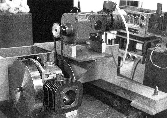
The next generation of velocity drives for BS spectroscopy was introduced again at the FRMI using a modified Fichtel & Sachs petrol motor used normally for concrete mixing machines. The photo below shows the first prototype. This crank shaft drive achieved speeds up to 1.5 m/s.
The next photo shows the drive developed by Alefeld for the first BS spectrometer in Jülich around 1970. It is a transparent drive using two modified lawn mover motors coupled together. The white beam traverses the BS monochromator mounted on a honey comb aluminum holder plate. A copy of this drive was installed on the first version of IN10. The drawback of the drive was its maximum speed limited to about 1 m/s.
![]()
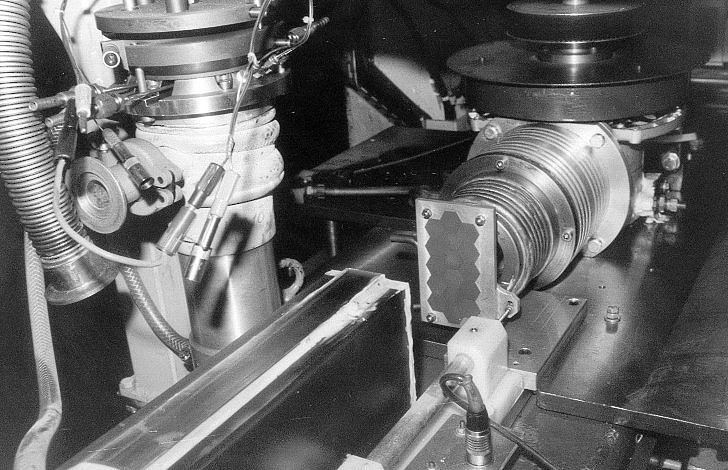
Therefore it was replaced later a ILL by an improved version of the Fichtel & Sachs drive from FRMI shown in the photo below: One sees the end of the neutron guide H15, the Si monochromator ( hexagonal structure) on an aluminum plate and behind the Doppler drive. The pickup coil to measure the velocity is also visible. Behind the neutron guide one sees the first cryofurnace for tests of the temperature scan of the BS monochromator ( about 1976).
High speed drive for a 'Bunching' X-TOF spectrometer
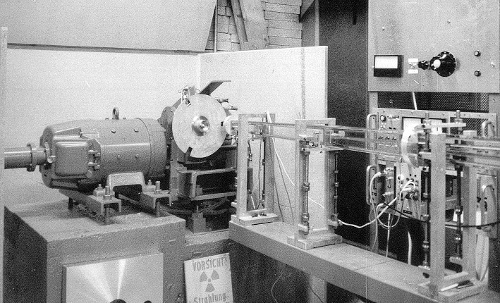
For the sake of completeness the photo below shows a prototype of a high speed velocity drive using a Honda motor bicycle motor. Speeds up to 25 m/s could be reached with 10000 rpm and an amplitude of 2.5 cm. The drive had been developed by Knauer ( Diplom Arbeit at the FRMI, E14, 1974). It was used to demonstrate the effect of 'bunching' ( time focussing) of neutrons. The monochromator mounted on the drive was a gypsum crystal. It suffered accelerations up to 3200g! The photo shows also the incoming and the outgoing neutron guides as well as a disk chopper with 3 windows. This disk has coupled mechanically with a gear ( reduction of a factor of 3 in frequency) to the Doppler drive. The windows were phased relative to the piston such that they were open only during the time the piston accelerated the monochromator towards the incoming neutron. So the first neutrons were caught up by the later coming neutrons because the latter had been reflected from the faster moving crystal. Intensity gain factors up to 30 could be achieved. With this drive an energy changes of +/- 160 µeV for neutrons at 6.27 Å were possible! The life time of this drive was hoever probably quite short but sufficient to perform the required test experiments in the frame of the diploma work!
Velocity drive of the BS spectrometer IN16 at the ILL
The velocity drive of IN16 consists of 2 piston motor drives syncronised by
belts to run in opposite phase (below left), one piston carrying the 5.5 kg
aluminium monochromator plate with 600 cm**2 Si crystals on a spherically
curved surface (below right, monochromator with deformed Si(111) crystals) the
other piston carries a counter weight (left side of left figure below). In total
12.5 kg are moved on a crankshaft, sinusoidal like velocity profile. In this
way balancing to first order is achieved allowing Doppler speeds up to 2.2 m/s
at a fixed amplitude of ± 25mm. The monochromator velocity is measured
by an induction linear transducer delivering an output voltage proportional
to the monochromator speed.
The velocity drive at the HFBS of NIST
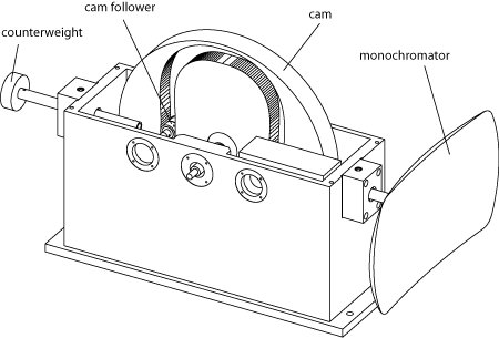
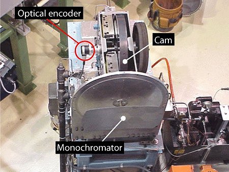
The velocity drive of the BS spectrometer at NIST achieves the highest velocities available today such that energy transfers up to +/- 50 µeV are possible at a wave length of 6.27 Å. In contrast to other backscattering spectrometers, the HFBS drive system is a cam-based one which allows the velocity profile of the motion to be determined by the shape of the cam. As implemented on the HFBS, the velocity profile of the monochromator is a rounded triangle. This shape avoids the large accelerations resulting from a pure triangle profile but still allows almost equal weighting to all energy transfers in the dynamic range. This is not possible with a conventional sinusoidal velocity profile (found in locomotive-type drives) which applies more weight to large energy transfers.
The Doppler drive is designed to achieve a top frequency of 25 Hz which corresponds to an acceleration in excess of 100 g's. The support structure is constructed from a graphite composite with a foam core to minimize the total mass of the assembly. In addition, the maximum deflection of the structure at the highest operating speed is designed to be less than 0.25 mm to keep the energy resolution as narrow as possible.
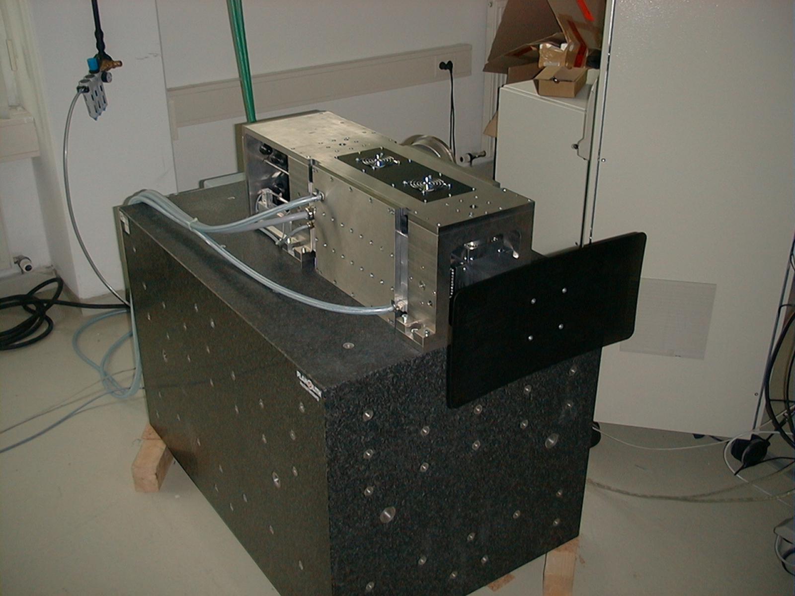
New linear motor based velocity drives built by AEROLAS
The photo below shows a 3D computer drawing of the
velocity drive installed on the new BS spectrometer at the FRMII and very recently
on IN16 at ILL. This drive was initiated by the FZ Jülich and was developed
by the small German company AEROLAS, Unterhaching. These drives are based on
linear motors (blue gray side plates below). The stators of these motors are
fixed on the rectangular surface coated carbon fibre piston (green below) which
is guided by two frames of air bearings with about 10 µm air gaps (AEROLAS
patent). In contrast to the IN16 Doppler the moving weights are not balanced
and therefore the drive is mounted on a 2200 kg granite block. A further development
to a weight compensated Doppler drive was envisaged for IN16, but failed due
to the high price.
The specifity of linear motor based drives is that they are in principle able
to run arbitray velocity profiles (sinusoidal, near triangular..) at a chosen
amplitude up to a maximal value. Accelerations are limited by the power of the
linear motor and the moving weights. Friction is minimal due to the air bearings
and therefore no lubrificants are needed. Power electronics, water cooling and
compressed air is needed for the functioning. With the linear drives at RSSM,
FRMII and IN16B monochromator speeds up to 4.7 m/s are possible at the maximum
amplitude of ± 75 mm.