
Page 81 - ILL Annual Report 2019
P. 81
MODERNISATION PROGRAMMES AND TECHNICAL DEVELOPMENTS
78-79
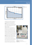
Figure 2
Flux gains: simulations (blue), measurements (red dots).
30.0
10.0
5.0 4.0 3.0
2.0 1.5 1.0 0.5
20.45 5.11
Energy [meV]
2.27 1.28 0.82 0.57 0.42
McStas Simulations Measurements
2 4 6 8 10 12 14 Wavelength [Å]
cannot benefit from the original 200 mm height as losses are significant in the vertical direction. The expected wavelength-dependent gain (an average gain factor
of around three) has been confirmed by measurements (figure 2). A more surprising consequence of the perfectly aligned new guide is the transport of high-energy neutrons in the beam. These were scarcely present before, and extra shielding has had to be installed to reduce their impact on the spectrum background.
Sample environment
It quickly became clear, after the first experiments on
single crystals on IN5, that a high-field magnet would
boost the study of magnetic materials. This was not new; such equipment exists on time-of-flight instruments at other neutrons centres. A design by Cryogenics Inc. (London,
UK) was chosen, featuring a large, horizontal, angular opening (almost 100 degrees horizontally and 30 degrees vertically) and a high maximum field (10 T). The magnet was ordered in 2015 but only became ready for use on the instrument at the beginning of 2019. Work was performed in the meantime to remove any magnetisable elements close to the sample area, such as the choppers’ steel base plates. Commissioning of the magnet with choppers in rotation (figure 3) revealed the need to reinforce the magnetic shielding against stray fields incompatible with the rotating aluminium disks. The shielding, made of Telar-57 soft iron, was calculated, designed and installed in-house.
The magnet was commissioned just before the first reactor cycle in 2019 and first used for regular experiments up to the maximum field of 10 T in July 2019. More experiments have now been scheduled for the next reactor cycles.
Neither of these projects would have been possible without the commitment of many inside and outside the ILL. They deserve to be warmly thanked for their contributions.
Figure 3
Magnet during commissioning in May 2019:
upper left) the magnet in place on IN5;
upper right) logbook and choppers monitoring;
lower right) Cryogenics power supply showing the achieved field (9.995 T~ 10 T).
www.ill.eu
Gain: New / reference
